Bumper systems for motor vehicles

A technology for bumpers and motor vehicles, which is applied in the field of bumper systems, can solve the problems that the force level cannot be fully predicted, the energy introduction cannot be fully predicted, and cannot be realized, so as to minimize subsequent costs, save resources, and reduce damage. small effect

Active Publication Date: 2019-05-14
BENTELER AUTOMOBILTECHNIK GMBH
View PDF8 Cites 0 Cited by
  • Summary
  • Abstract
  • Description
  • Claims
  • Application Information

AI Technical Summary

Problems solved by technology

[0004] However, in the two patent documents mentioned at the outset, due to the attachment of the bracket to the bumper beam, a force of a defined magnitude in the case of an AZT load with a correspondingly defined introduction of energy into the bumper system levels are not sufficiently predictable
This is particularly difficult when an aluminum profile is used as the bumper cross member, which is relatively soft and initially deforms uncontrollably on the order of millimeters of deformation under load, so that it is impossible or only impossible to achieve Fully predictable energy introduction and small interventions into the bumper system

Method used


Image

  • Bumper systems for motor vehicles
  • Bumper systems for motor vehicles
  • Bumper systems for motor vehicles

Examples


Embodiment Construction

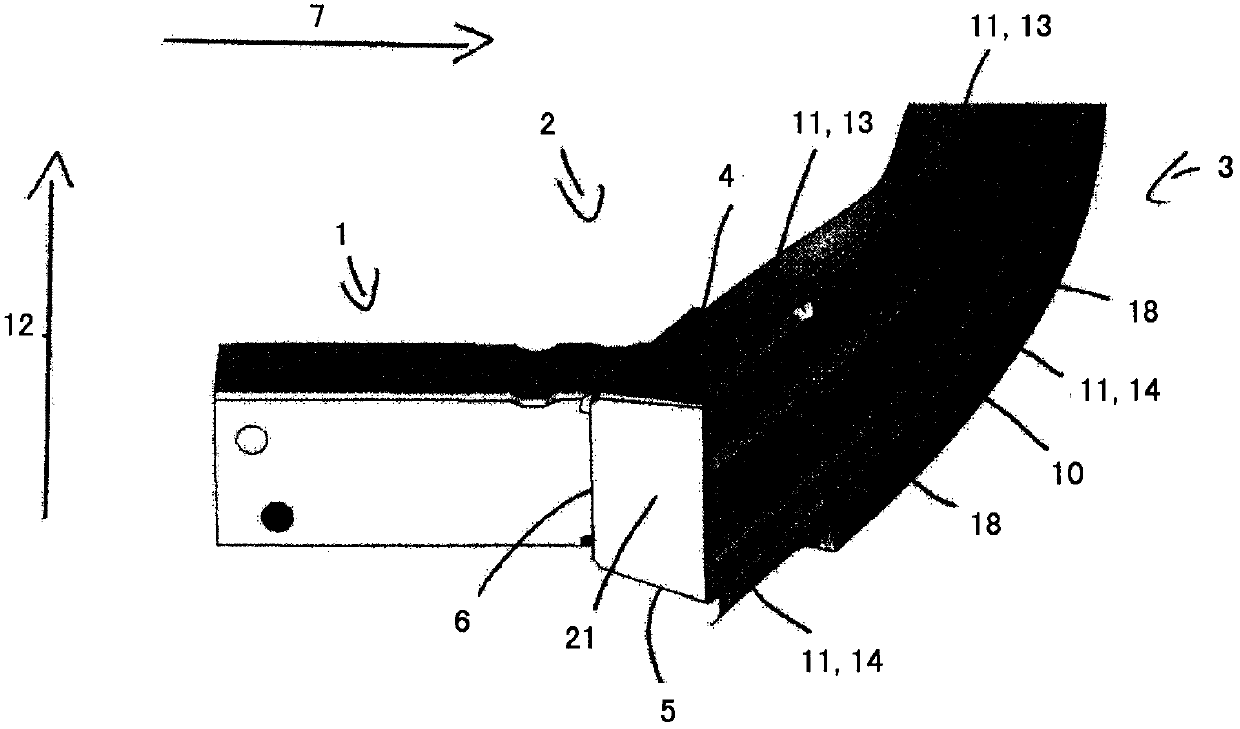
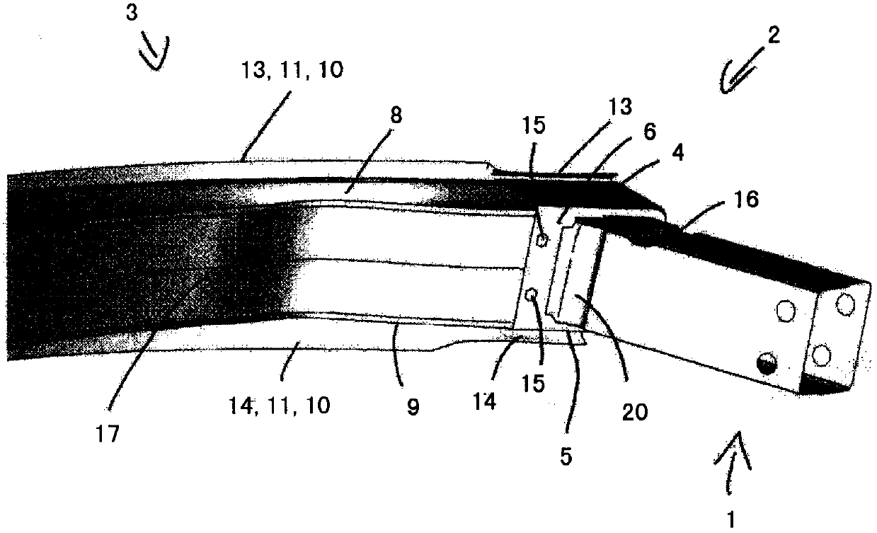
[0028] exist Figure 9 and 10 An exemplary embodiment of a bumper system for a motor vehicle according to the invention is shown in a wireframe model, wherein the bumper system here has a bumper beam 3 which is designed as a multi- Cavity parts. The bumper beam 3 here has an upper boundary wall 8 , a lower boundary wall 9 as well as a bumper beam front wall 10 and a bumper beam rear wall 17 .

[0029] The bumper cross member 3 is here substantially rectangular and is bent or curved over its longitudinal extent. In this case, inside the bumper beam 3 , which is designed as a multi-chamber profile, a corrugated intermediate wall 19 is arranged, which connects the bumper beam front wall 10 to the bumper beam rear wall 17 . In this case, the intermediate wall 19 is arranged in the center of the bumper cross member 3 .

[0030] The bumper beam front wall 10 here has two continuous grooves 18 over its entire longitudinal extent, which increase the stability of the bumper beam 3 ...


PUM


Abstract

The invention concerns a bumper system for a motor vehicle with at least one crashbox, which is arranged by means of a bracket on a bumper cross member, wherein the bracket is provided with a first bracket plate and a second bracket plate, while the first bracket plate bears at least partly against a first limiting element and the second bracket plate against a second limiting element of the bumper cross member, wherein the bumper cross member is taken up in the bracket such that the first bracket plate and / or the second bracket plate extends in the direction of the vehicle longitudinal axis over at least ¾ preferably over 9 / 10 of the bumper cross member in the direction of a bumper cross member front wall, especially preferably entirely up to the bumper cross member front wall.

Description

technical field [0001] The invention relates to a bumper system for a motor vehicle. Background technique [0002] Such a bumper system is known, for example, from DE 10 2004 013 713 A1 and DE 10 2004 056 249 A1. In the above two patent documents, a C-shaped bracket is welded to the crash box, and the C-shaped bracket is arranged on the bumper beam. In this case, the C-shaped bracket profile of such a bumper system is arranged by means of an upper bracket plate and a lower bracket plate in the region of the rear of the upper and lower boundary walls of the bumper beam facing the center of the vehicle. . In this case, the mounting of the bracket on the bumper cross member takes place by means of a releasable screw connection. By means of this screw connection, the bumper cross member can be released from the bracket, which is particularly advantageous if the bumper cross member has to be replaced as a result of a motor vehicle accident. [0003] Such bumper systems for mo...

Claims


Application Information

Patent Timeline
Patent Type & Authority Patents(China)
IPC IPC(8): B60R19/18B60R19/34
CPCB60R19/34B60R19/24
Inventor C·汉丁M·帕阿雷
Owner BENTELER AUTOMOBILTECHNIK GMBH
Why Eureka
Try Eureka