Electrostatic transducer, method for connecting the same and manufacturing method

a technology of electrostatic transducers and manufacturing methods, applied in the direction of electrostatic transducers, electrical transducers, electrical apparatus, etc., can solve the problems of cumbersome attachment procedures, and achieve the effects of large electrostatic transducer assemblies, fast and simple manufacturing, and more effective multi-layer electrostatic transducers

Inactive Publication Date: 2006-11-02
PANPHONICS OY
View PDF11 Cites 2 Cited by
  • Summary
  • Abstract
  • Description
  • Claims
  • Application Information

AI Technical Summary

Benefits of technology

[0021] Different embodiments of the invention may provide considerable advantages. An advantage is that transducers may form large electrostatic transducer assemblies. Another advantage is that it is fast and simple to manufacture a module-like structure, since the manufacture of an electrostatic transducer may be automated and fewer manufacturing molds for transducers are needed. Another advantage is also that the module-like structure allows an electrical connection to be provided between the desired module elements, whereby transducers or transducer assemblies may be controlled separately. Still another advantage is that the transducer is an electrically safe component, because the conducting layer of the transducer is hidden in the recess. Consequently, the transducer need not be screened electrically, although no other transducer is connected next to it. Yet another advantage is that the switching connector can be utilized in various ways, such as for providing phase shifts or for other similar passive activity. On the other hand, the switching connector may include either filters, amplifiers or other similar useful solutions. Another advantage is also that individual or module-containing electrostatic transducers may be arranged on top of one another to provide more effective multilayer electrostatic transducers.

Problems solved by technology

A problem with the solution of the reference is, however, that attaching loudspeaker modules to one another requires a complex structure, which makes the attachment procedure cumbersome.

Method used


Image

  • Electrostatic transducer, method for connecting the same and manufacturing method
  • Electrostatic transducer, method for connecting the same and manufacturing method
  • Electrostatic transducer, method for connecting the same and manufacturing method

Examples


Embodiment Construction

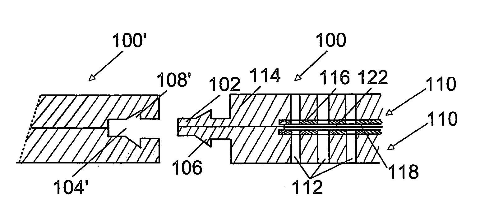
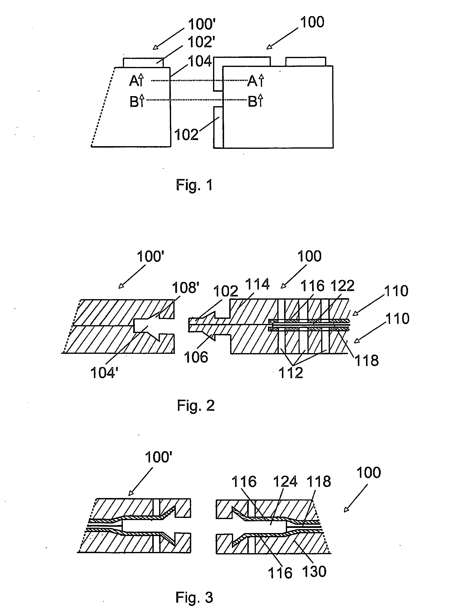
[0031]FIG. 1 shows a top view of a plate-like electrostatic transducer 100 according to an embodiment of the invention. The electrostatic transducer 100 comprises at least one fastening edge. In the embodiment of FIG. 1, the transducer 100 comprises, on its two outer sides, a protrusion-like fastening edge, what is known as a male edge 102, and on its two other outer sides a notch-like fastening edge, what is known as a female edge 104. The electrostatic transducer 100 is arranged to be fastened to a second electrostatic transducer 100′ by inserting the male edge 102 into the female edge 104′. By connecting electrostatic transducers 100, 100′ to one another, module-containing transducer assemblies may be manufactured in a fast and simple manner. The figure also includes two intersections A-A, B-B, which are explained in connection with FIGS. 2 and 3.

[0032]FIG. 2 shows the intersection A-A of the plate-like electrostatic transducer 100 according to an embodiment of the invention sho...


PUM


Abstract

An electrostatic transducer, a method for connecting the same and a manufacturing method. The electrostatic transducer comprises at least one stator, which comprises an insulating layer and a conducting layer, and a film element which is arranged to vibrate in response to voltage supplied to it and which is provided in such a manner that an air gap is formed between the conducting layer and the film element. The electrostatic transducer also comprises at least one fastening edge arranged on the outer edge of the electrostatic transducer, the fastening edge being arranged to be fastened to a fastening element of a second electrostatic transducer.

Description

FIELD OF THE INVENTION [0001] The invention relates to an electrostatic transducer comprising at least one stator, which comprises an insulating layer and a conducting layer, a film element which is arranged to vibrate in response to voltage supplied to it and which is provided in such a manner that an air gap is formed between the conducting layer and the film element. [0002] The invention also relates to a method for connecting an electrostatic transducer to a second electrostatic transducer, the electrostatic transducer comprising at least one stator, which comprises an insulating layer and a conducting layer, and a film element which is arranged to vibrate in response to voltage supplied to it and which is provided in such a manner that an air gap is formed between the conducting layer and the film element. [0003] The invention further relates to a method for manufacturing an electrostatic transducer, the method comprising forming an insulating layer of a stator, arranging a con...

Claims


Application Information

Patent Timeline
Patent Type & Authority Applications(United States)
IPC IPC(8): H04R25/00
CPCH04R1/06H04R31/006H04R19/00
Inventor KYNNOS, KIMMO
Owner PANPHONICS OY
Why Eureka
Try Eureka