Method for manufacturing a membrane assembly for a fuel cell with catalyst free edge areas; membrane assembly and fuel cell with membrane assembly

a manufacturing method and fuel cell technology, applied in the direction of fuel cells, sustainable manufacturing/processing, climate sustainability, etc., can solve the problems of prone to failures at the edge between the frame and the catalyst layer, current membrane assemblies, membrane electrode frame assemblies in particular, and achieve the effect of easy separation and easy adjustmen

Active Publication Date: 2021-12-14
FORD MOTOR CO +1
View PDF2 Cites 0 Cited by
  • Summary
  • Abstract
  • Description
  • Claims
  • Application Information

AI Technical Summary

Benefits of technology

[0019]According to a further development of the invention it is envisaged that the pressing is carried out in a continuous process by two rollers pressing the compression pad and the second decal layer against each other. In other words the membrane can be supplied moving to the two rollers as well as both catalyst layers can be supplied from a different side of the membrane into the two rollers. So the membrane and the first and the second decal layer are supplied independently into the two rollers. On the other side of the two rollers the membrane assembly with both catalyst layers arranged on their respective side of the membrane leaves the rollers. The membrane and the decal layers can be supplied in form of a respective belt. On the other side of the two rollers a continuous belt of multiple membrane assemblies along a moving direction of the belt can be supplied. A continuous process is very effective for large scale productions of the membrane assembly.
[0020]According to a further development the compression pad is a protruding part of one of the two pressing surfaces or one of the two rollers. In other words the compression pad can easily be separated from the two pressing surfaces or the two rollers or be part of the pressing surfaces or the two rollers. The compression pad may be formed like a stamp protruding of one of the two pressing surfaces or one of the two rollers. It may also be envisaged that both pressing surfaces or both rollers comprise a respective compression pad.
[0021]According to a further development it is envisaged that the first decal layer forms the first catalyst layer only in an area of the first side of the membrane which is overlapped by the compression pad during the step of pressing the compression pad and the second decal layer against each other, and / or the second decal layer forms the second catalyst layer only in an area of the second side of the membrane which is overlapped by the compression pad during the step of pressing the compression pad and the second decal layer against each other. In other words the first decal layer and / or the second decal layer are only formed in the areas overlapped by the compression pad during the step of pressing. In other words the respective catalyst layer is stamped from the respective decal layer on the respective side of the membrane by the compression pad. Therefore the position and shape of the respective decal layers can easily be adjusted by the compression pad.

Problems solved by technology

Current membrane assemblies, membrane electrode frame assemblies in particular, are proned to failures at an edge between the frame and the catalyst layers.
Such failures can be caused by chemical degradation in the region where the catalyst layer and the frame face each other.

Method used


Image

  • Method for manufacturing a membrane assembly for a fuel cell with catalyst free edge areas; membrane assembly and fuel cell with membrane assembly
  • Method for manufacturing a membrane assembly for a fuel cell with catalyst free edge areas; membrane assembly and fuel cell with membrane assembly
  • Method for manufacturing a membrane assembly for a fuel cell with catalyst free edge areas; membrane assembly and fuel cell with membrane assembly

Examples


Embodiment Construction

[0047]In the figures the same elements or elements having the same function are indicated by the same reference signs.

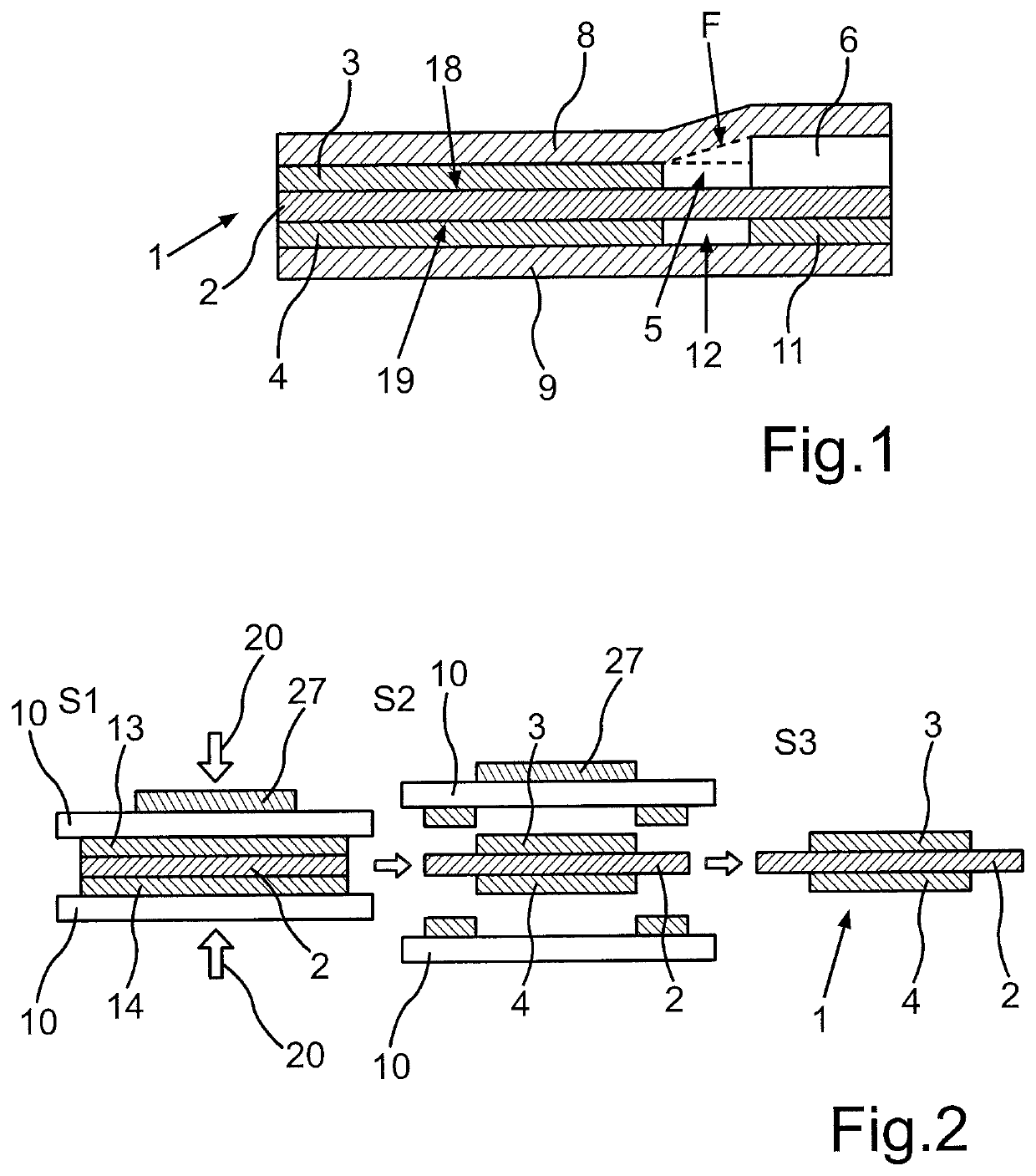
[0048]FIG. 1 shows a membrane assembly 1 comprising a membrane 2 and catalyst layers 3, 4 on both sides 18, 19 of the membrane 2. On both sides the membrane assembly 1 is coated is with a gas diffusion layer 8, 9. The respective gas diffusion layers 8, 9 can be either considered a part of the membrane assembly 1 or not part of the membrane assembly 1. Also a frame 6 is arranged on the membrane 2 to provide sufficient stiffness for the membrane for usage in a fuel cell.

[0049]The membrane 2, which can also referred to as electrolyte, has a first side 18 and a second side 19. The membrane 2 can permeable or semi-permeable to enable an exchange of ions and / or molecules between the first side 18 and the second side 19. A first catalyst layer 3 is arranged on the first side 18 of the membrane 2. A second catalyst layer 4 is arranged on the second side 19 of the membrane 2....


PUM

PropertyMeasurementUnit
thickaaaaaaaaaa
sizeaaaaaaaaaa
sizeaaaaaaaaaa

Abstract

A method for manufacturing a membrane assembly for a fuel cell. To overcome a problem of chemical degradation at an edge of the membrane, the method comprises the following steps:
    • positioning a first decal layer, which is made of the same material as a first catalyst layer, on a first side of the membrane,
    • positioning a second decal layer, which is made of the same material as a second catalyst layer, on a second side of the membrane,
    • pressing a compression pad, which is positioned on the first decal layer with the first decal layer and the second decal layer fully overlapping the compression pad, and the second decal layer against each other with the first decal layer and the membrane positioned in-between, whereby pressure on the first and the second decal layer is applied only in an area covered by the compression pad.

Description

BACKGROUND OF THE INVENTIONField of the Invention[0001]The invention relates to a method for manufacturing a membrane assembly for a fuel cell, which membrane assembly comprises a membrane with a first side and a second side, and a first catalyst layer arranged on the first side of the membrane and a second catalyst layer arranged on the second side of the membrane, wherein the first catalyst layer and the second catalyst are at least substantially fully overlapping each other with respect to their extension parallel to the membrane. Another aspect of the present invention relates to a membrane assembly for a fuel cell which is manufactured by the above mentioned method. A further aspect of the invention relates to a fuel cell with said membrane assembly.Description of the Related Art[0002]Membrane assemblies, also often referred to as membrane electrode assembly (MEA), are well-known for usage in a fuel cell. If such a membrane assembly comprises a frame, it is also referred to a m...

Claims


Application Information

Patent Timeline
Patent Type & Authority Patents(United States)
IPC IPC(8): H01M8/00H01M8/1004H01M4/88
CPCH01M8/1004H01M4/881H01M4/8814H01M4/8896H01M2008/1095Y02P70/50Y02E60/50
Inventor PRASS, SEBASTIANGHUMAN, MANPALLEOW, ANDREWEASTCOTT, JENNIETHOMAS, OWEN
Owner FORD MOTOR CO
Why Eureka
Try Eureka