Pivot shaft structure moving around virtual axis

a shaft and virtual axis technology, applied in the direction of instruments, portable computer details, electric apparatus casings/cabinets/drawers, etc., can solve the problems of large assembling tolerance and high cost, and achieve the effect of reducing the assembling/motional space of components, simplified structure and reduced volum

Active Publication Date: 2021-02-18
FIRST DOME
View PDF0 Cites 0 Cited by
  • Summary
  • Abstract
  • Description
  • Claims
  • Application Information

AI Technical Summary

Benefits of technology

[0009]It is therefore a primary object of the present invention to provide a pivot shaft structure moving around virtual axis, which is applicable to a flexible screen to reduce assembling / motional space of the components. The pivot shaft structure moving around virtual axis has a simplified structure and smaller volume. The pivot shaft structure moving around virtual axis includes an assembly of a main body, a first operation board and a second operation board disposed on the main body. The first operation board has an arm section. The second operation board has an arm section. The arm sections of the first and second operation boards are respectively received in a first arched rail and a second arched rail of the main body. The first and second arched rails are arched and disposed around a virtual axis. When a user operates the first operation board or the second operation board to move, the first operation board or the arm section thereof and the second operation board or the arm section thereof respectively synchronously move around the virtual axis along the first and second arched rails toward each other to achieve opening / closing effect. The arm section of the first operation board and the arm section of the second operation board cooperate with the first and second arched rails to together define a space in the closing operation for receiving the bent section of a flexible screen. This improves the shortcomings of the conventional pivot shaft device that the structure is complicated and it is troublesome to manufacture and assemble the components and the assembling tolerance is large and the cost is high.

Problems solved by technology

This improves the shortcomings of the conventional pivot shaft device that the structure is complicated and it is troublesome to manufacture and assemble the components and the assembling tolerance is large and the cost is high.

Method used


Image

  • Pivot shaft structure moving around virtual axis
  • Pivot shaft structure moving around virtual axis
  • Pivot shaft structure moving around virtual axis

Examples


Embodiment Construction

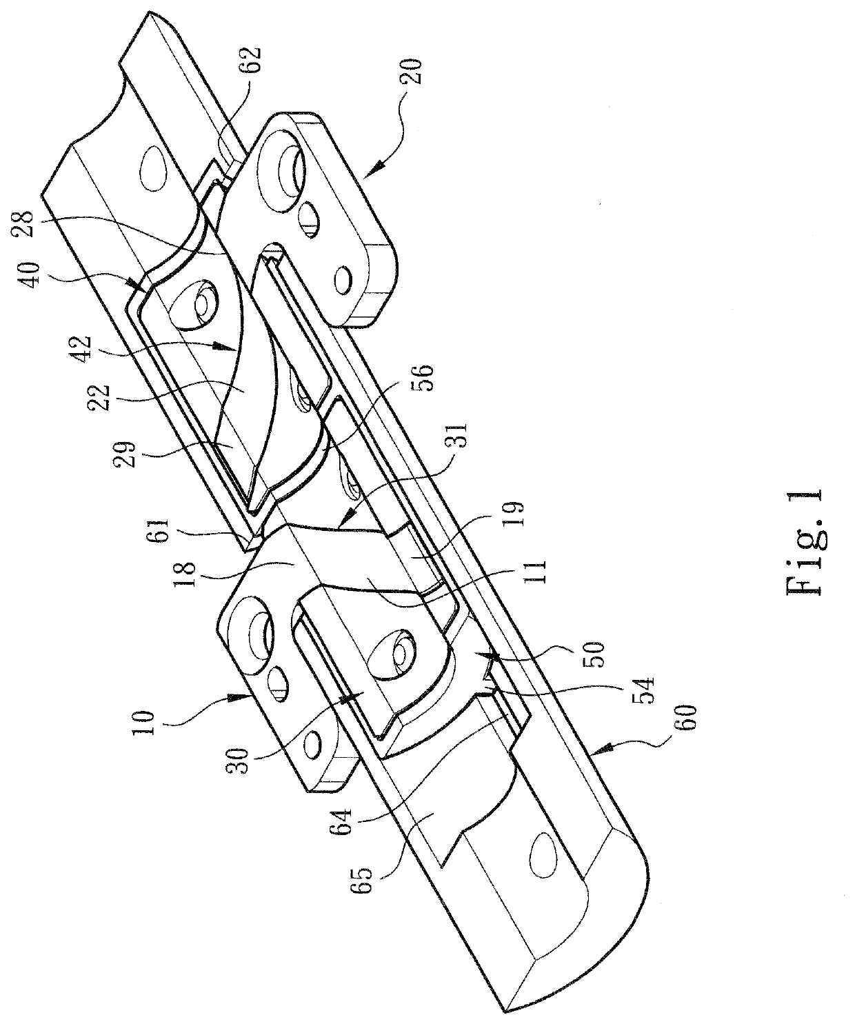
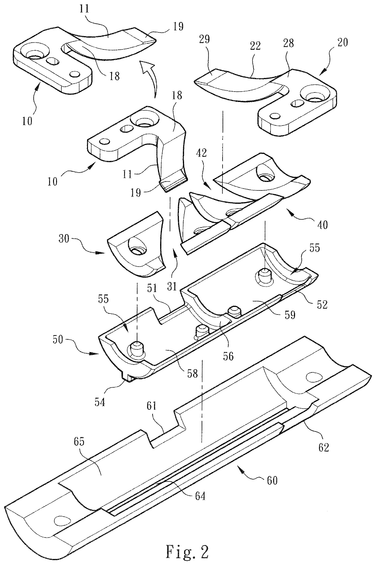
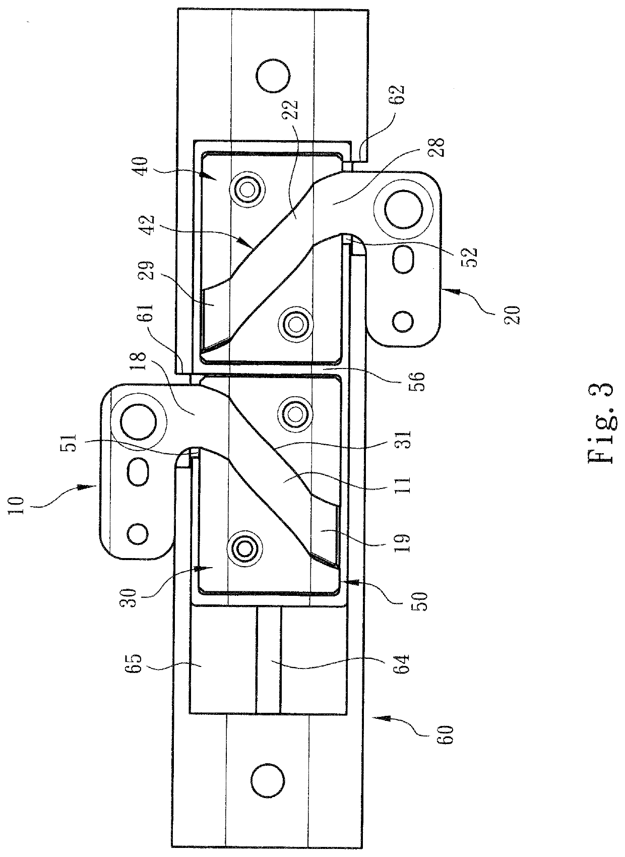
[0022]Please refer to FIGS. 1, 2 and 3. The pivot shaft structure moving around virtual axis of the present invention includes an assembly of a main body 50, a first operation board 10 and a second operation board 20. The upper section, upper side, bottom section, lower side, left end, left side, right end, right side, etc. mentioned hereinafter are recited with the direction of the drawings as the reference direction.

[0023]As shown in the drawings, the main body 50 is an arched plate body or a cylindrical (or substantially semi-cylindrical) body. The main body 50 has an open chamber 55 with an arched (cross-sectional) structure. A diaphragm 56 is selectively disposed in a substantially middle position of the chamber 55 to partition the chamber 55 into a first (arched) cavity 58 and a second (arched) cavity 59. In addition, the upper side (with reference to the drawings) of the main body 50 is formed with a first notch 51 in communication with the first cavity 58. The lower side of ...


PUM


Abstract

The pivot shaft structure moving around virtual axis includes an assembly of a main body, a first operation board and a second operation board disposed on the main body. The first operation board has an arm section. The second operation board has an arm section. The arm sections of the first and second operation boards are respectively received in a first arched rail and a second arched rail of the main body. The first and second arched rails are arched and disposed around a virtual axis. When a user operates the first operation board or the second operation board to move, the first operation board or the arm section thereof and the second operation board or the arm section thereof respectively synchronously move around the virtual axis along the first and second arched rails toward each other to achieve opening/closing effect.

Description

BACKGROUND OF THE INVENTION1. Field of the Invention[0001]The present invention relates generally to a pivot shaft structure, and more particularly to a pivot shaft structure moving around virtual axis, in which the operation boards of the pivot shaft move around a virtual axis to reduce the assembling / motional space of the components.2. Description of the Related Art[0002]There are various electronic apparatuses provided with covers or display screens, such as mobile phones, notebooks, PDA and electronic books. The covers or display screens are pivotally mounted on the electronic apparatuses via pivot pins or rotary shafts, whereby the covers or the display screens can be freely rotated and opened / closed under external force. For example, Taiwanese Patent No. 97222022 “rotary shaft structure” and Taiwanese Patent No. 98207366 “pivot shaft structure” disclose typical embodiments.[0003]In order to operate the display module (such as the screen) and / or the apparatus body module of the...

Claims


Application Information

Patent Timeline
Patent Type & Authority Applications(United States)
IPC IPC(8): G06F1/16
CPCG06F1/169H04M1/0218G06F1/1681H04M1/0216H05K5/0226H04M1/0243B25G3/38E05Y2900/606
Inventor HSU, AN SZU
Owner FIRST DOME
Why Eureka
Try Eureka