Transmitter apparatus

a technology of transmission apparatus and delay, which is applied in the direction of transmission monitoring, baseband system details, modulation, etc., can solve the problems of not preventing the deterioration of transmission quality, difficult for a common user to adjust synchronization, and using a circuit with a delay too large to negl

Inactive Publication Date: 2006-11-02
PANASONIC CORP
View PDF24 Cites 35 Cited by
  • Summary
  • Abstract
  • Description
  • Claims
  • Application Information

AI Technical Summary

Benefits of technology

[0011] With the above-described constitution, a delay difference is computed by the delay difference computing means based on the signal corresponding to the amplitude and the signal corresponding to the phase, which are produced by the polar signal producing means, and the amplitude signal and the phase signal, which are detected by the amplitude / phase detecting means and the timings of the amplitude signal and the phase signal are adjusted by the timing adjusting means based on the obtained delay difference. With this, it is possible to adjust the delay difference between the amplitude signal and the phase signal and hence to automatically adjust the synchronization of the amplitude signal and the phase signal. Further, the amplitude / phase detecting means detects the amplitude signal and the phase signal, for example, just before the amplitude modulation amplifying means. With this, it is possible to make the delay difference of the amplitude signal and the phase signal between the detection position and the amplitude modulation amplifying means smaller than a delay difference required from the transmitting characteristics of ACLR and EVM.
[0032] According to the invention, it is possible to provide a transmitting apparatus capable of automatically adjusting the synchronization of the amplitude signal and the phase signal in a transmitting apparatus using polar modulation.

Problems solved by technology

However, the first conventional example shown in FIG. 13 does not have timing adjusting means and hence can not correct the delay difference in path between the amplitude signal and the phase signal and hence can not prevent the deterioration of transmission quality caused by the delay difference.
Moreover, it is difficult for a common user to adjust synchronization when the user uses a product after the product is shipped.
However, to detect the synchronization between the amplitude signal and the phase signal by such a configuration, a signal in an RF band needs to be demodulated into a base band by some means, which results in using a circuit having a delay that is too large to neglect such as low pass filter.
As a result, this may vary delay at the time of detection and reduce the accuracy of detection of delay.

Method used


Image

  • Transmitter apparatus
  • Transmitter apparatus
  • Transmitter apparatus

Examples


Embodiment Construction

[0050] In this embodiment, one example of a polar modulation transmitting apparatus corresponding to a transmitting apparatus using polar modulation, and a synchronization circuit and a synchronization adjusting method of an amplitude signal and a phase signal in this polar modulation transmitting apparatus will be described.

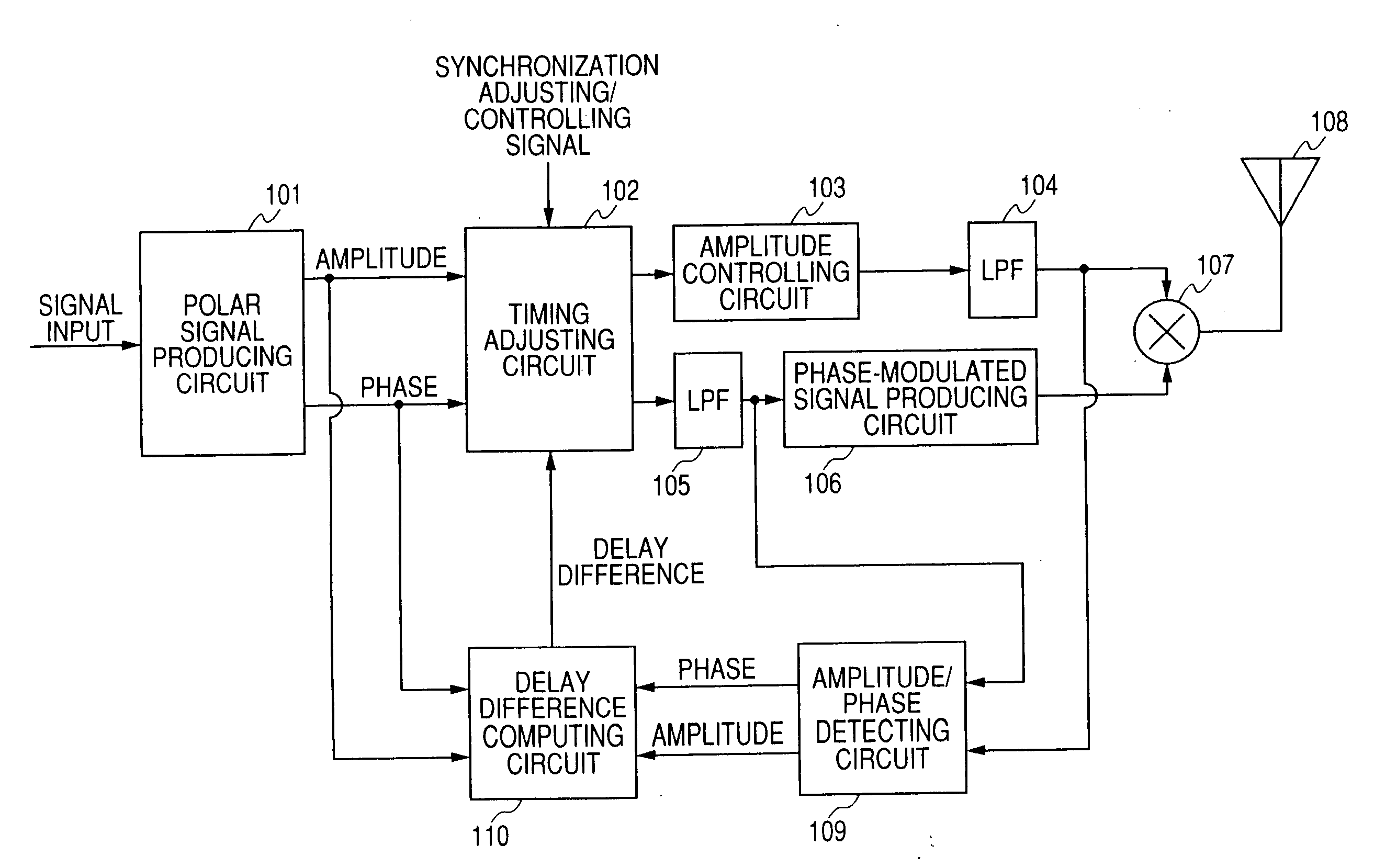
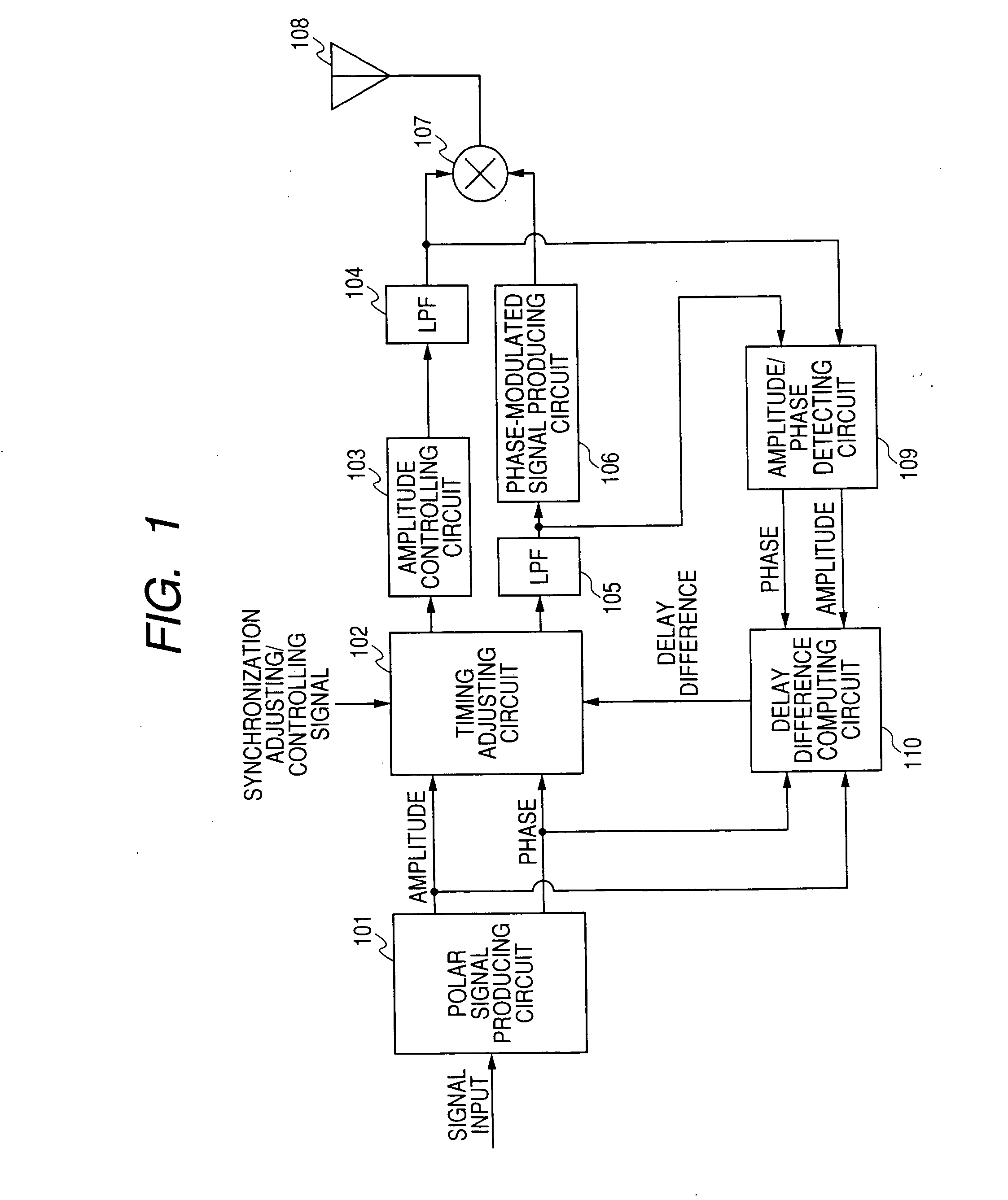
[0051]FIG. 1 is a block diagram showing the construction of a polar modulation transmitting apparatus in accordance with an embodiment of the present invention. The polar modulation transmitting apparatus of this embodiment is constructed of a polar signal producing circuit 101, a timing adjusting circuit 102, an amplitude controlling circuit 103, low pass filters 104 and 105, a phase-modulated signal producing circuit 106, a multiplying circuit 107, a transmitting antenna 108, an amplitude / phase detecting circuit 109, and a delay difference computing circuit 110.

[0052] In the polar modulation transmitting apparatus constructed in this manner, the polar signal...


PUM


Abstract

The object of the present invention is to automatically adjust the synchronization of an amplitude signal and a phase signal in a transmitting apparatus such as polar modulation transmitting apparatus. A polar signal producing circuit (101) produces signals corresponding to the amplitude and the phase of a transmitting modulated wave from an input signal and multiplies the amplitude signal by the phase signal by a multiplying circuit (107) to amplitude modulate a phase-modulated wave to produce a transmitting modulated wave and radiates this transmitting modulated wave as radio wave from an antenna (108). An amplitude / phase detecting circuit (109) detects an amplitude signal and a phase signal from the input of the multiplying circuit (107) and the input of a phase-modulated signal producing circuit (106). A delay difference computing circuit (110) computes a correlation function between the amplitude signal produced by the polar signal producing circuit and the amplitude signal detected by the amplitude / phase detecting circuit and a correlation function between the phase signal produced by the polar signal producing means and the phase signal detected by the amplitude / phase detecting means, and computes a delay difference between the amplitude signal and the phase signal from maximum values of the respective correlation functions. Then, a timing adjusting circuit (102) adjusts the delay time between the amplitude signal and the phase signal on the base of the computed delay difference.

Description

TECHNICAL FIELD [0001] The present invention relates to a transmitting apparatus using a polar modulation applied to a radio communication apparatus. BACKGROUND ART [0002]FIG. 13 shows the first conventional example of a polar modulation transmitting apparatus. The polar modulation transmitting apparatus has a polar signal producing circuit 1201, an amplitude controlling circuit 1202, a phase-modulated signal producing circuit 1203, and a non-linear power amplifier 1204. In such a polar modulation transmitting apparatus, the polar signal producing circuit 1201 produces a signal corresponding to the amplitude and the phase of a transmitting modulated wave from an input signal, and the amplitude controlling circuit 1202 and the phase-modulated signal producing circuit 1203 produce an amplitude signal and a phase-modulated signal, respectively, based on this signal. While the non-linear power amplifier 1204 is operated in a non-linear saturation mode and has the phase modulated signal ...

Claims


Application Information

Patent Timeline
Patent Type & Authority Applications(United States)
IPC IPC(8): H04B1/02H03C1/52H03F1/02H03F1/06H03F1/32H03F3/24H04B1/04H04B1/707H04B1/7073H04B14/00
CPCH03F1/02H03F1/0205H03F1/3241H04B14/008H03F1/3282H03F3/24H04B1/0475H03F1/3247
Inventor UDAGAWA, MASAHARUARAYASHIKI, MAMORU
Owner PANASONIC CORP
Why Eureka
Try Eureka