Thermally conductive element for cooling an air gap inductor, air gap inductor including same and method of cooling an air gap inductor

a technology of thermally conductive elements and air gaps, applied in basic electric elements, lighting and heating apparatus, electrical equipment, etc., can solve the problems of increased gap loss, increased gap loss, and increased heating

Inactive Publication Date: 2006-11-09
HONEYWELL INT INC
View PDF31 Cites 36 Cited by
  • Summary
  • Abstract
  • Description
  • Claims
  • Application Information

AI Technical Summary

Problems solved by technology

This so-called “flux fringing” generates eddy currents in the core elements which result in gap loss and the generation of additional heat, particularly at certain hot spots near the air gap where the flux reenters the core.
However, larger air gaps produce more flux fringing and thus a higher gap loss and more heating.
This generation of excess heat makes it difficult to adequately cool the inductor.
However, materials with suitable thermal conductivities are often electrically conductive.
Placing electrically conductive materials in the flux, however, leads to the formation of eddy currents therein and produces energy losses.

Method used


Image

  • Thermally conductive element for cooling an air gap inductor, air gap inductor including same and method of cooling an air gap inductor
  • Thermally conductive element for cooling an air gap inductor, air gap inductor including same and method of cooling an air gap inductor
  • Thermally conductive element for cooling an air gap inductor, air gap inductor including same and method of cooling an air gap inductor

Examples


Embodiment Construction

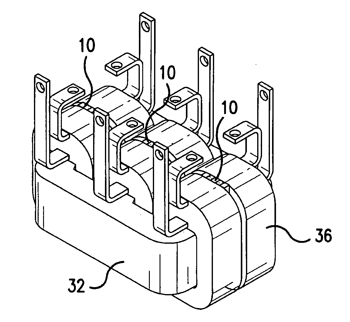
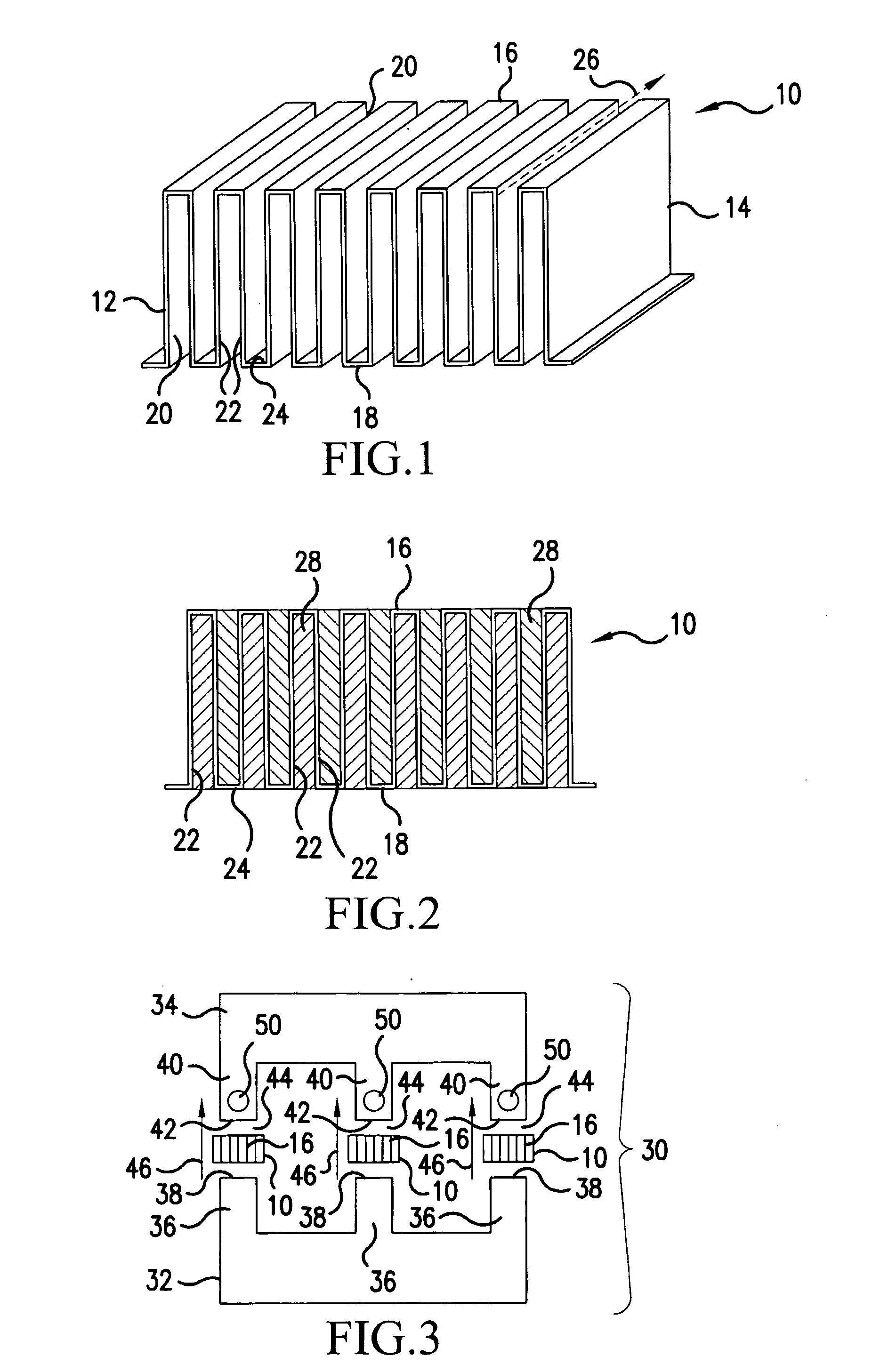
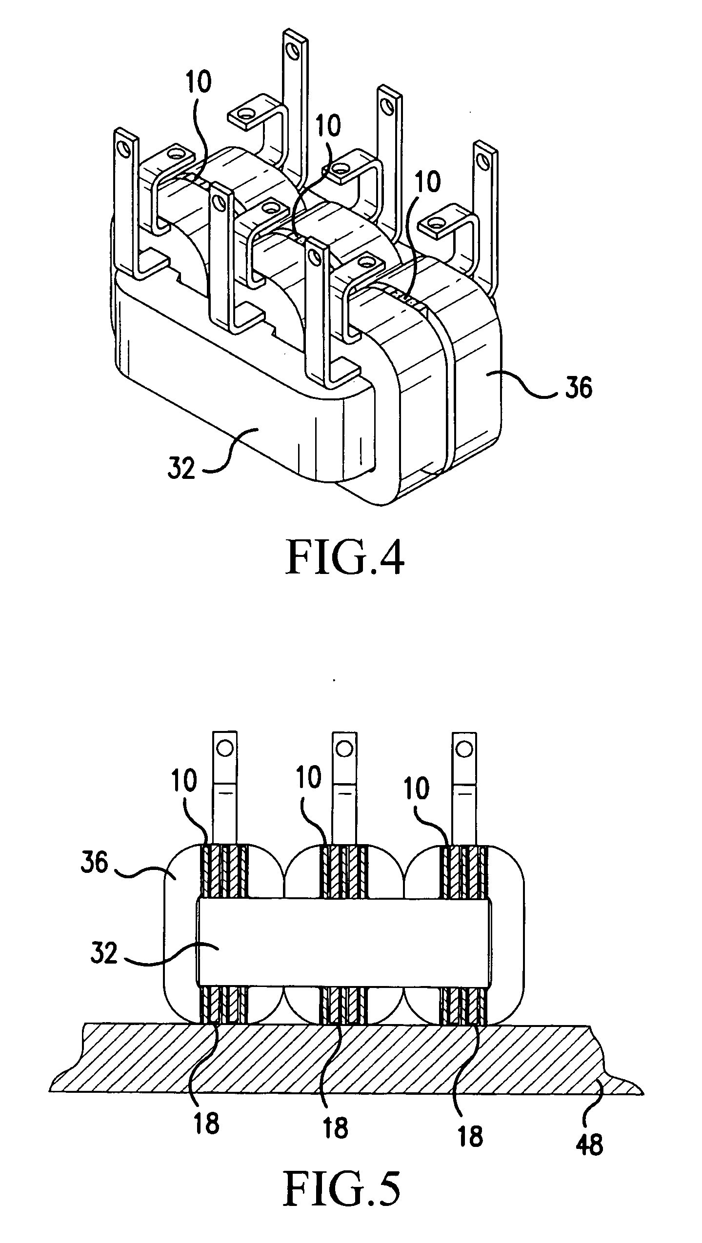
[0024] Referring now to the drawings, wherein the showings are for the purpose of illustrating preferred embodiments of the present invention only, and not for the purpose of limiting same, FIG. 1 illustrates a heat transfer device 10 having a first side 12, a second side 14, a top 16 and a bottom 18. The distance from first side 12 to second side 14 may be referred to herein as the depth of heat transfer device 10; the distance from top 16 to bottom 18 may be referred to as the height of the heat transfer device 10.

[0025] Heat transfer device 10 is formed from a sheet of material repeatedly folded back on itself to form a series of folds 20 (or molded or cast in such a form) each fold 20 comprising a pair of primary walls 22 extending from first side 12 to second side 14 and from top 16 to bottom 18 of device 10 and a single connecting wall 24 connecting adjacent ones of primary walls 22. Device 10 is formed so that, looking in the direction from first side 12 to second side 14, i...


PUM

PropertyMeasurementUnit
thicknessaaaaaaaaaa
operating temperatureaaaaaaaaaa
angleaaaaaaaaaa

Abstract

An inductor including a magnetic core (30) including at least one magnetic core element (32), the magnetic core (30) having a first portion (38) spaced from and facing a second portion (42), at least one winding (36) supported by the magnetic core (30), and a thermally conductive element (10) having a thermal conductivity greater than about 100 w / mK in thermal contact with the first and second portions (38, 42), the electrically conductive element (10) defining a plurality of paths (26) from the first portion (38) to the second portion (42), the paths (26) being filled with an electrically insulative material (28). A method of cooling an inductor with a heat transfer device (10) is also disclosed.

Description

FIELD OF THE INVENTION [0001] The present invention is directed to an improved cooling structure for an air gap inductor, an air gap inductor including same, and a method of cooling an air gap inductor, and, more specifically, toward a cooling structure for an air gap inductor adapted to conductively convey heat away from an inductor hot spot caused by flux fringing, an inductor including such a cooling element and to a method for dissipating heat caused by flux fringing. BACKGROUND OF THE INVENTION [0002] Air gap inductors include a core formed from one or more core elements that are made from a magnetic material and often formed from a plurality of stacked laminations. These core elements support electric windings, which produce a magnetic flux in the core in a well known manner. [0003] The core elements define one or more magnetic paths which include at least one air gap. The core includes at least one first face and at least one second face on opposite sides of the air gap, and ...

Claims


Application Information

Patent Timeline
Patent Type & Authority Applications(United States)
IPC IPC(8): H01F27/06
CPCF28D2021/0029F28F3/02F28F3/025H01F27/306H01F3/14H01F27/22H01F27/2876F28F2265/24
Inventor DE, SUKUMARTHOMSON, MARK A.VORMBAUM, MANFREDSAXENA, SUNIT
Owner HONEYWELL INT INC
Why Eureka
Try Eureka