Lightweight shielded panel system including acoustical shielding

Inactive Publication Date: 2006-11-16
VILLANELLA DAN
View PDF13 Cites 2 Cited by
  • Summary
  • Abstract
  • Description
  • Claims
  • Application Information

AI Technical Summary

Benefits of technology

[0008] The present invention provides a composite panel structure for electrically shielding against radio frequency and which also exhibits improved acoustical capabilities. The composite panel is a component in a lightweight shielded panel system. Such composite panel includes a honeycomb type core member formed from a first predetermined material and having each of a first predetermined thickness, a first predetermined width and a first predetermined length. There is a metallic skin layer formed from a second predetermined material disposed on each face of such honeycomb type core member. Such skin layer has each of a second predetermined thickness, a second predetermined width and a second predetermined length. Additionally, there is an outer perimeter frame formed from a third predetermined material. Such outer perimeter has each of a third predetermined thickness, a third predetermined width and a third predetermined length. OBJECTS OF THE INVENTION
[0011] Still another object of the present invention is to provide a composite type panel for use in constructing a shielded enclosure having improved acoustical characteristics.
[0012] Yet another object of the present invention is to provide a composite type panel for use in constructing a shielded enclosure which is relatively lightweight.
[0013] A further object of the present invention is to provide a composite type panel for use in constructing a shielded enclosure which will exhibit relatively high performance characteristics.

Problems solved by technology

Additionally, most of these prior art type panels that are utilized in making a radio frequency shielded enclosure are relatively heavy and generally are not well designed from an acoustical standpoint.

Method used


Image

  • Lightweight shielded panel system including acoustical shielding
  • Lightweight shielded panel system including acoustical shielding

Examples


Embodiment Construction

[0017] Prior to proceeding to the more detailed description of the present invention, it should be noted that, for the sake of clarity and understanding, identical components which have identical functions have been identified with identical reference numerals throughout the different views illustrated in the drawing Figures.

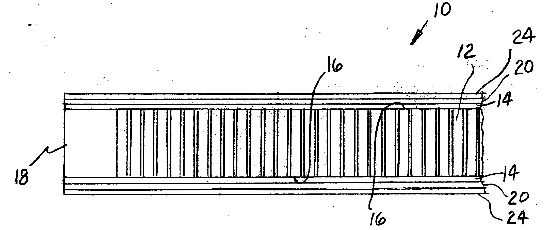
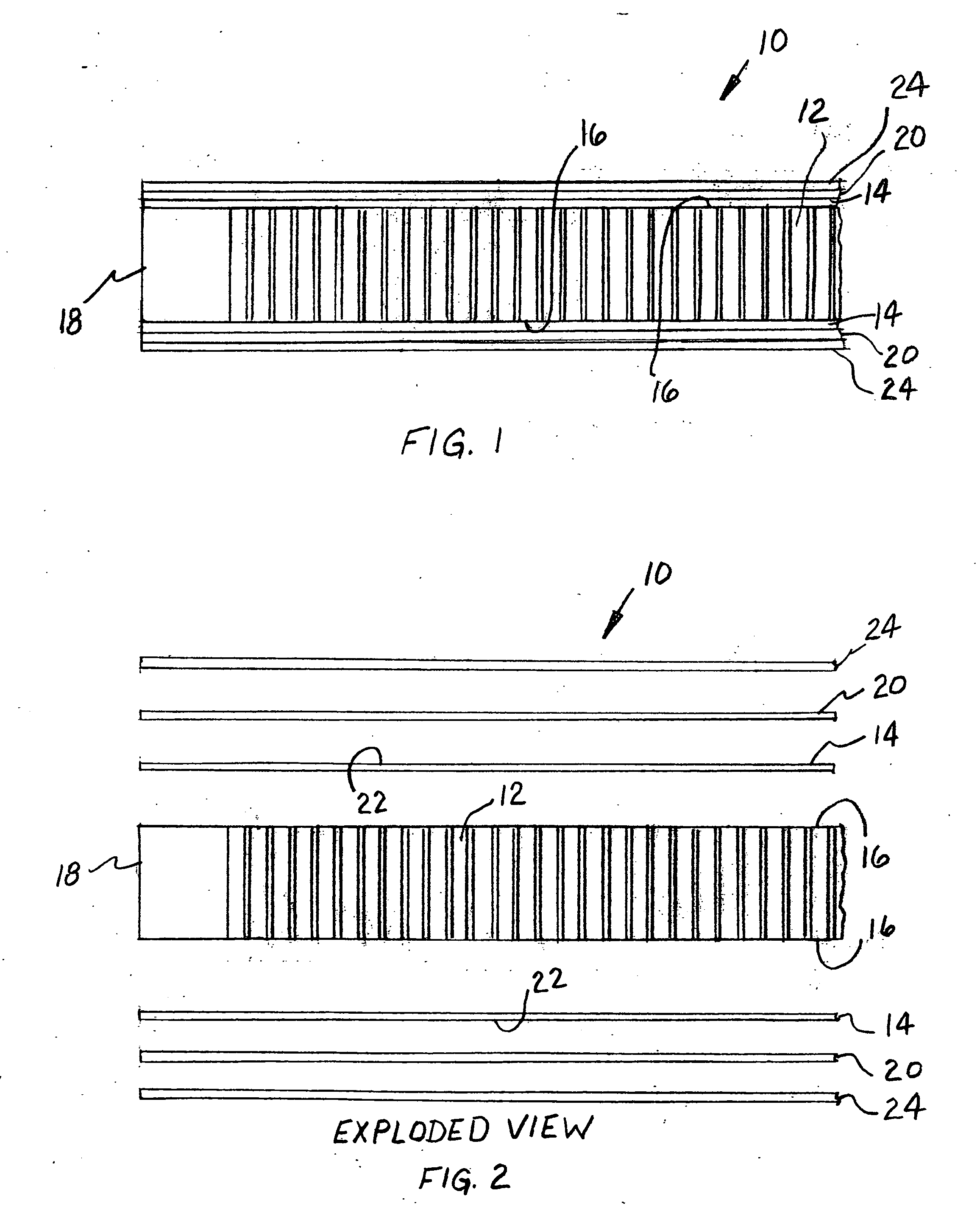
[0018] Reference is now made to the drawing Figures wherein there is illustrated a presently preferred embodiment of a composite, generally designated 10, for use as a relatively lightweight shielding material to construct an enclosure which is shielded against undesirable radio frequencies and which can be constructed to exhibit excellent acoustical characteristics.

[0019] Such composite 10 includes a honeycomb type core member 12 formed from a first predetermined material. The honeycomb type core member 12 has each of a first predetermined thickness, a first predetermined width and a first predetermined length.

[0020] In the presently preferred embodiment of ...


PUM

PropertyMeasurementUnit
Thicknessaaaaaaaaaa
Thicknessaaaaaaaaaa
Thicknessaaaaaaaaaa

Abstract

A composite panel for a lightweight shielded panel system. Such panel includes a honeycomb type core member formed from a first predetermined material and having each of a first predetermined thickness, a first predetermined width and a first predetermined length. A skin layer is formed from a second predetermined material and disposed on each face of such honeycomb type core member. The has each of a second predetermined thickness, a second predetermined width and a second predetermined length. There is also an outer perimeter frame formed from a third predetermined material and which has each of a third predetermined thickness, a third predetermined width and a third predetermined length.

Description

CROSS REFERENCE TO RELATED APPLICATION [0001] This application is closely related to and claims priority from U.S. Provisional Patent Application Ser. No. 60 / 680,748 filed May 13, 2006.FIELD OF THE INVENTION [0002] The present invention relates, in general, to a panel particularly designed for shielding radio frequencies and, more particularly, this invention relates to a lightweight modular type panel for a shielding system which has high performance and acoustical shielding characteristics incorporated therein. BACKGROUND OF THE INVENTION [0003] Prior to the conception and development of the present invention, it has been known in the prior art to provide shielding of enclosures against detrimental radio frequencies. Most of the prior art type panels which are known to applicant have incorporated in them various materials some of which contain wood products. [0004] Additionally, most of these prior art type panels that are utilized in making a radio frequency shielded enclosure ar...

Claims


Application Information

Patent Timeline
IPC IPC(8): E04C2/54
CPCB32B3/12H05K9/0088B32B15/08B32B15/082B32B15/085B32B15/18B32B15/20B32B2307/102B32B2457/00B32B2457/08E04B1/86E04B2001/748E04B2001/925E04C2/365E04C2/384B32B15/043
Inventor VILLANELLA, DAN
Owner VILLANELLA DAN
Why Eureka
Try Eureka