Work Surface Device

a technology for working surfaces and devices, applied in the field of work surfaces, can solve the problems of shortening the work surface and the device often does not increase the available work surface area

Inactive Publication Date: 2006-11-16
GOLDBERG STEVEN LANE +1
View PDF19 Cites 14 Cited by
  • Summary
  • Abstract
  • Description
  • Claims
  • Application Information

AI Technical Summary

Benefits of technology

[0014] Other features and advantages of the present invention will become more readily apparent to those

Problems solved by technology

There is often a shortage of work surfaces for performing various tasks in many work or home environments.
Work surfaces and cutting board devices are known for use in

Method used


Image

  • Work Surface Device
  • Work Surface Device
  • Work Surface Device

Examples


example 1

[0061] Restaurants often have busy, crowded kitchens, with little extra counter space. The present invention satisfies several needs. Prepared food items are placed on a sheet pan or in a container sitting on the present invention thus increasing valuable workspace in the kitchen. The dimensions of the work surface 110 are such that one full sheet pan, two half sheet pans, full or half cutting boards, or the custom cutting board of FIG. 13 may be placed on the work surface. In one embodiment, dimensions of work surface 110 are of the order of 19¼ inches by 27¼ inches. By placing pans or containers onto surface 110 rather than on a standard 6 in. by 30 in. prep table, 20% more work space can be provided.

[0062] In one example, a work board is placed on the apparatus and vegetables chopped and the waste swept through the aperture into the waste container below. Alternatively, a bowl is placed in the aperture and the chopped vegetables on the work board transferred from the work board ...

example 2

[0063] In offices and copy rooms, supplies are often stored in boxes in cabinets and shelves. However it is not uncommon for counter space to be taken up by supplies or another person's work. The present invention is placed conveniently by a commonly used piece of machinery, such as a photocopier. This provides a place to put down documents being copied or small office supplies such as paper clips, staple removers, tape dispensers, and the like, while facilitating disposal of waste without disrupting the work placed on the device.

example 3

[0064] In machine shops, there is often a need for a convenient waste container but there is limited space. In such an application, the present invention is placed next to each machinist's work space. While providing a convenient waste disposal container, the present invention also provides a convenient place for holding tools and things such as nuts, bolts and screws. In addition, it is common in machine shops to wash mechanical components in solvents. The present invention provides a support for cleaning the components as well as convenient waste disposal directly below the work surface.

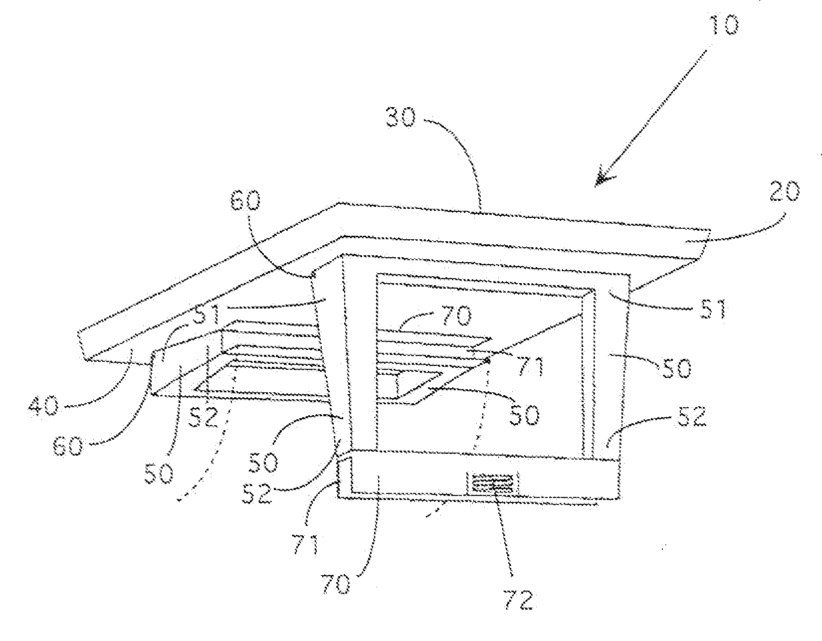
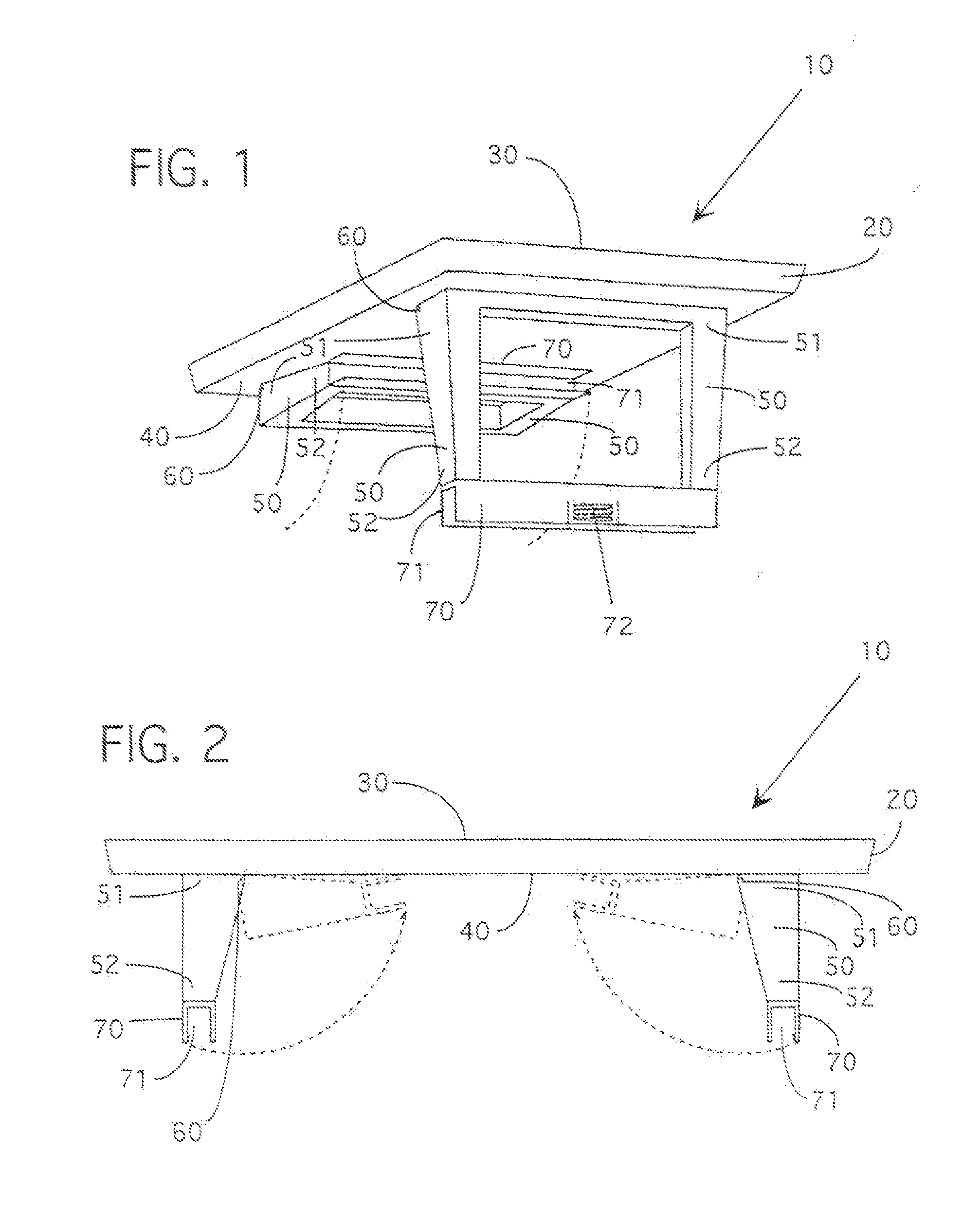
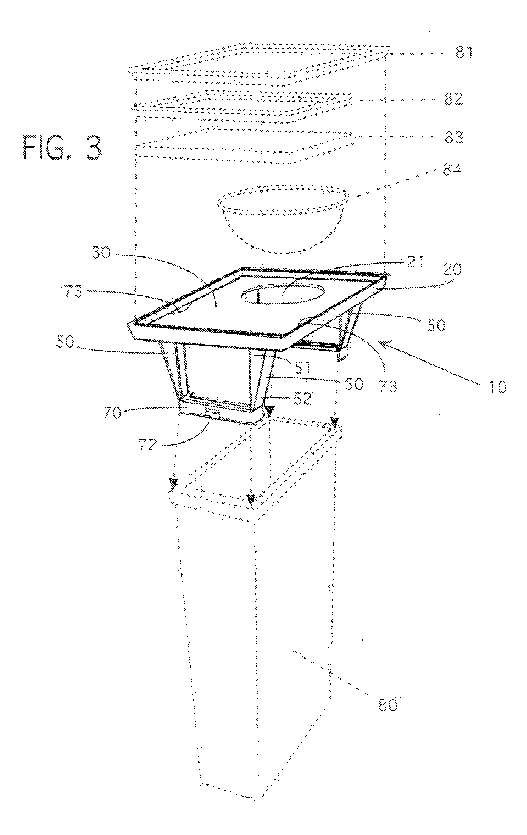
[0065] Although the work surface device of the previous embodiments is intended to be secured to the rim of any type of container, it will be understood that the work surface device is supported by other means in alternative embodiments. In one embodiment, as illustrated in FIG. 18, the work surface device 160 is a stand-alone work table with extended legs 162 for engaging the ground and supportin...


PUM


Abstract

A work surface device has an upper member with a substantially planar top surface. A support is secured to the upper member for supporting the upper member on a support member with the planar top surface in a generally horizontal orientation. The support has a fastener or clamping device at its lower end for releasable engagement with a portion of the support member. A work board of shape and dimensions generally matching the shape and dimensions of the top surface may be placed on the top surface. The work board and upper member have aligned openings in which a receptacle may be seated or through which waste may be discarded into a container beneath the work surface. In one arrangement, the clamping device is secured to the upper rim of a container with the work surface spaced above the open upper end of the container.

Description

RELATED APPLICATIONS [0001] The present application is a continuation-in-part of co-pending U.S. patent application Ser. No. 10 / 768,246 filed on Jan. 30, 2004 which is incorporated herein by reference in its entirety, which is a continuation of U.S. Pat. No. 6,745,702 issued on Jun. 8, 2004, which is also incorporated herein by reference in its entirety.BACKGROUND [0002] 1. Field of the Invention [0003] The present invention relates generally to work surfaces for use in many work and home environments. [0004] 2. Related Art [0005] There is often a shortage of work surfaces for performing various tasks in many work or home environments. For example, in a home or restaurant kitchen, work surfaces are needed for food preparation such as cutting up vegetables, preparing fish or meat, chopping various foods, and the like. Work surfaces are also needed for gardening, flower arranging both by a commercial florist and in the home, decorating, automobile maintenance, and the like. Work surfa...

Claims


Application Information

Patent Timeline
IPC IPC(8): A47B37/00
CPCA47B23/001B65F1/14B65F1/10A47J47/005
Inventor GOLDBERG, STEVEN LANEBERKOVITZ, PHILLIP JAY
Owner GOLDBERG STEVEN LANE
Why Eureka
Try Eureka