Communication method

a communication method and packet technology, applied in the field of packet communication, can solve problems such as packet loss and packet sequence error, and achieve the effect of no wasteful latency tim

Inactive Publication Date: 2006-11-16
NEC CORP
View PDF9 Cites 44 Cited by
  • Summary
  • Abstract
  • Description
  • Claims
  • Application Information

AI Technical Summary

Benefits of technology

[0110] In the present invention, taking the sequencing and the retransmitting control independently and assigning the retransmission ID to a unit for allowing the packet loss to be detected at an earliest stage, in the packet communication, makes it possible to detect the packet loss at an earlier stage as compared with the retransmitting control that is taken flow by flow, accompanied by the conventional sequencing.
[0111] Also, according to the present invention, also in the sequencing per flow, the effect that no wasteful latency time of the packet of a certain flow due to a loss of the packet of other flow is generated, thus allowing the packet to be transferred is obtained.
[0112] Also, in the present invention, the path to be utilized for the transmission and the retransmitting control are independent of each other, so no problem occurs as a whole of the system also in a case where a certain path failed in communication.

Problems solved by technology

In a case where two nodes make packet communication over an internet, a packet loss and a packet sequence error occur.

Method used


Image

  • Communication method
  • Communication method
  • Communication method

Examples


embodiment 1

[0171] The embodiment 1 of the present invention will be explained.

[0172] In the embodiment 1, a case where the transmitting node and the receiving node are connected via one path will be explained.

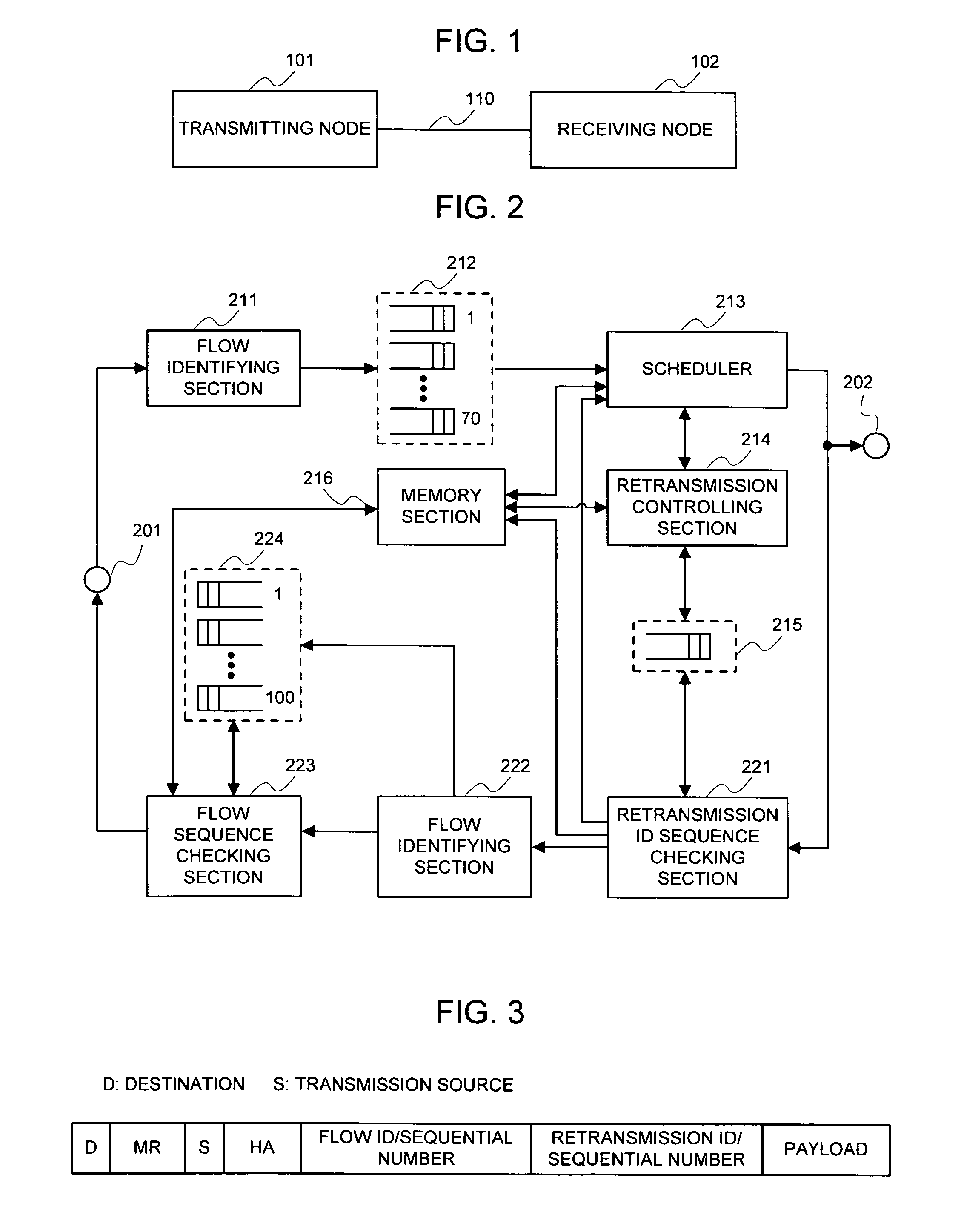
[0173] Upon making a reference to FIG. 1, the embodiment 1 of the present invention is comprised of a transmitting node 101, a receiving node 102, and a path 110 for making a connection between the nodes. The path 110 is a packet communication network such as an internet. Additionally, both of the communication, which is made to the receiving node 102 from the transmitting node 101, and the communication, which is made to the transmitting node 101 from the receiving node 102, can be considered. For a convenience of explanation, the nodes are named as a transmitting / receiving node respectively; however their functions are identical.

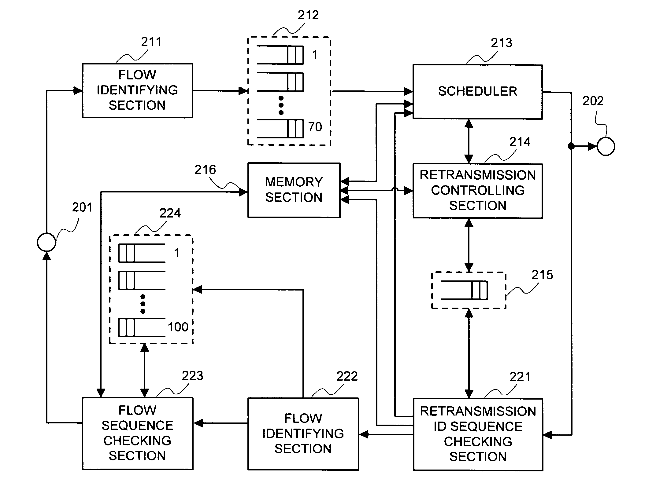
[0174] Next, a configuration of the transmitting node 101 will be explained.

[0175]FIG. 2 is a view illustrating the configuration of the transmitting node 1...

embodiment 2

[0228] The embodiment 2 of the present invention will be explained.

[0229] In the embodiment 2, a case will be explained where there exist a plurality of the paths for connecting the transmitting node and the receiving node.

[0230]FIG. 5 is a configuration view in a case where there exist a plurality of the paths for connecting the transmitting node and the receiving node.

[0231] Upon making a reference to FIG. 5, the embodiment 2 is comprised of a transmitting node 301, a receiving node 302, and M paths 312-1 to 312-M for making a connection between the nodes. Each of the paths 312-1 to 312-M is a packet communication network such as an internet. The so-called case where a plurality of the paths, i.e. M paths exist is a case where both of the transmitting node 301 and the receiving node 302 or one of them hold a plurality of communication interfaces. For example, it is a case where either the transmitting node 301 or the receiving node 302 has M communication interfaces, or a case ...

embodiment 3

[0249] The embodiment 3 of the present invention will be explained.

[0250] The embodiment 3 is fully identical to the embodiment 2 in terms of an arrangement of the nodes and a functional configuration of the node; however only a process is different of deciding the retransmission ID for the transmission packet in the transmitting node, so it will be explained below.

[0251] In the embodiment 3, the path and the retransmission ID, which do not correspond one to one, can be altered freely. Normally, in a case where a plurality of the paths are collected into a mass having one retransmission ID, there is a possibility that the arrival sequence of the packet at the moment that the receiving node receives the packet is remarkably disordered, depending upon delays of respective paths belonging to its retransmission ID, or a delay dispersion. For this, algorithm will be explained for deciding a plurality of the paths belonging to one retransmission ID such that a provability that the arriv...


PUM


Abstract

A first identifier for identifying each flow belonging to a first group relating to a sequencing, a first sequential number, said first sequential number being unique within each flow of the first group flow, a second identifier for identifying a flow relating to a retransmitting control, and a second sequential number, said second sequential number being unique within each flow belonging to the second group flow, are affixed to a transmission packet to transmit it. A receiving node makes a request for retransmission based upon the second identifier and the second sequential number, and a transmitting node retransmits its packet. Also, in the sequencing of the packets, the receiving node takes a sequencing of the packet based upon the first identifier and the first sequential number.

Description

APPLICABLE FIELD IN THE INDUSTRY [0001] The present invention relates to a packet communication between the two nodes in which a flow exists, and more particularly to a retransmitting control. BACKGROUND ART [0002] In a case where two nodes make packet communication over an internet, a packet loss and a packet sequence error occur. As a method of coping with the packet loss, a technology of a retransmitting method of the packet has been proposed (for example, a patent document 1). In the technology of the patent document 1, a flow control and a sequencing of the transmission packet are taken between a transmitting node and a receiving node; however in a case a wait for sequence occurred in the receiving node due to the packet loss, if the packet, which was an object of a wait for sequence, was not received within a fixed time, the transmitting node is notified of a request for retransmitting the packet which is an object of a wait for sequence. [0003] Also, in a case where a plurali...

Claims


Application Information

Patent Timeline
Patent Type & Authority Applications(United States)
IPC IPC(8): H04L12/56H04L1/16H04L1/18H04L45/80H04L47/22H04L47/43H04M3/00
CPCH04L1/1887H04L1/1642H04L1/18
Inventor NAKATA, TSUNEOONO, MASAHIRO
Owner NEC CORP
Why Eureka
Try Eureka