
Test method, test circuit, test circuit building-in device, and computer program

a test method and test circuit technology, applied in the field of test methods, test circuits, test circuit building-in devices, and computer programs, can solve the problems of wasting time waiting until the test of other blocks is competed, and achieve the effect of reducing the time spent waiting for the test period and reducing the waste of tim

Inactive Publication Date: 2006-11-16
OKI ELECTRIC IND CO LTD
View PDF4 Cites 0 Cited by
  • Summary
  • Abstract
  • Description
  • Claims
  • Application Information

AI Technical Summary

Benefits of technology

[0017] In the test according to the above article (1), there is no malfunction by the voltage drop thereof, the test period becomes longer, though. At the same time, in the test according to the above article (2), the test time is short, the peak current can not be reduced when the test period is short, however. Additionally, in the test according to the above article (3), there is no malfunction by the voltage drop thereof, because the test of every phase is done in serial. Moreover, the retention test is conducted only twice, and then the test time can be shortened. But, the effect of shortened test time becomes smaller as the number of blocks becomes larger.
[0018] The present invention is thought up from the above mentioned problems. Then the object of the invention is providing a new and revised test method, test circuit, test circuit building-in device, and computer program, being capable to shorten the test time and casing no problems of the voltage drop thereof at the same time.
[0020] According to the above test, the waste of time for waiting till the test of other blocks are competed can be reduced, by carrying out the phase test of every block in serial and carrying out the retention test immediately after the phase test of every block is completed. And then the test period can be shortened. In other words, the status of waiting for completing of the test of other blocks, for example, the status of neglecting the output though the signal inputs into the circuit, or the status of no change of input signal like the retention test, can be eliminated. Subsequently, the test can be done for the test time as long as the parallel test, and the problem of the voltage drop never occurs, comparing with the conventional test methods.
[0022] According to the above test, the waste of time for waiting till the test of other blocks are competed can be reduced, by carrying out the phase test of every block in serial and carrying out the retention test immediately after the phase test of every block is completed. And then the test period can be shortened. In other words, the status of waiting for completing of till the test of other blocks, for example, the status of neglecting the output though the signal inputs into the circuit, or the status of no change of input signal like the retention test, can be eliminated. Subsequently, the test can be done for the test period as long as the parallel test, and the problem of the voltage drop never occurs, comparing with the conventional test methods.
[0024] According to the above building-in test circuit device, the waste of time for waiting till the test of other blocks are competed can be reduced, by carrying out the phase test of every block in serial and carrying out the retention test immediately after the phase test of every block is completed. And then the test period can be shortened. In other words, the status of waiting for completing of the test of other blocks, for example, the status of neglecting the output though the signal inputs into the circuit, or the status of no change of input signal like the retention test, can be eliminated. Subsequently, the test can be done for the test period as long as the parallel test, and the problem of the voltage drop never occurs, comparing with the conventional test methods.
[0027] As described before, according to the present invention, the waste of time for waiting till the test of other blocks are competed can be reduced, by carrying out the phase test of every block in serial and carrying out the retention test immediately after the phase test of every block is completed. And then the test period can be shortened. In other words, the status of waiting for completing of the test of other blocks, for example, the status of neglecting the output though the signal inputs into the circuit, or the status of no change of input signal like the retention test, can be eliminated. Subsequently, the test can be done for the test period as long as the parallel test, and the problem of the voltage drop never occurs, comparing with the conventional test methods.

Problems solved by technology

However, the above technology includes the following problems.

Method used


Image

  • Test method, test circuit, test circuit building-in device, and computer program
  • Test method, test circuit, test circuit building-in device, and computer program
  • Test method, test circuit, test circuit building-in device, and computer program

Examples


Embodiment Construction

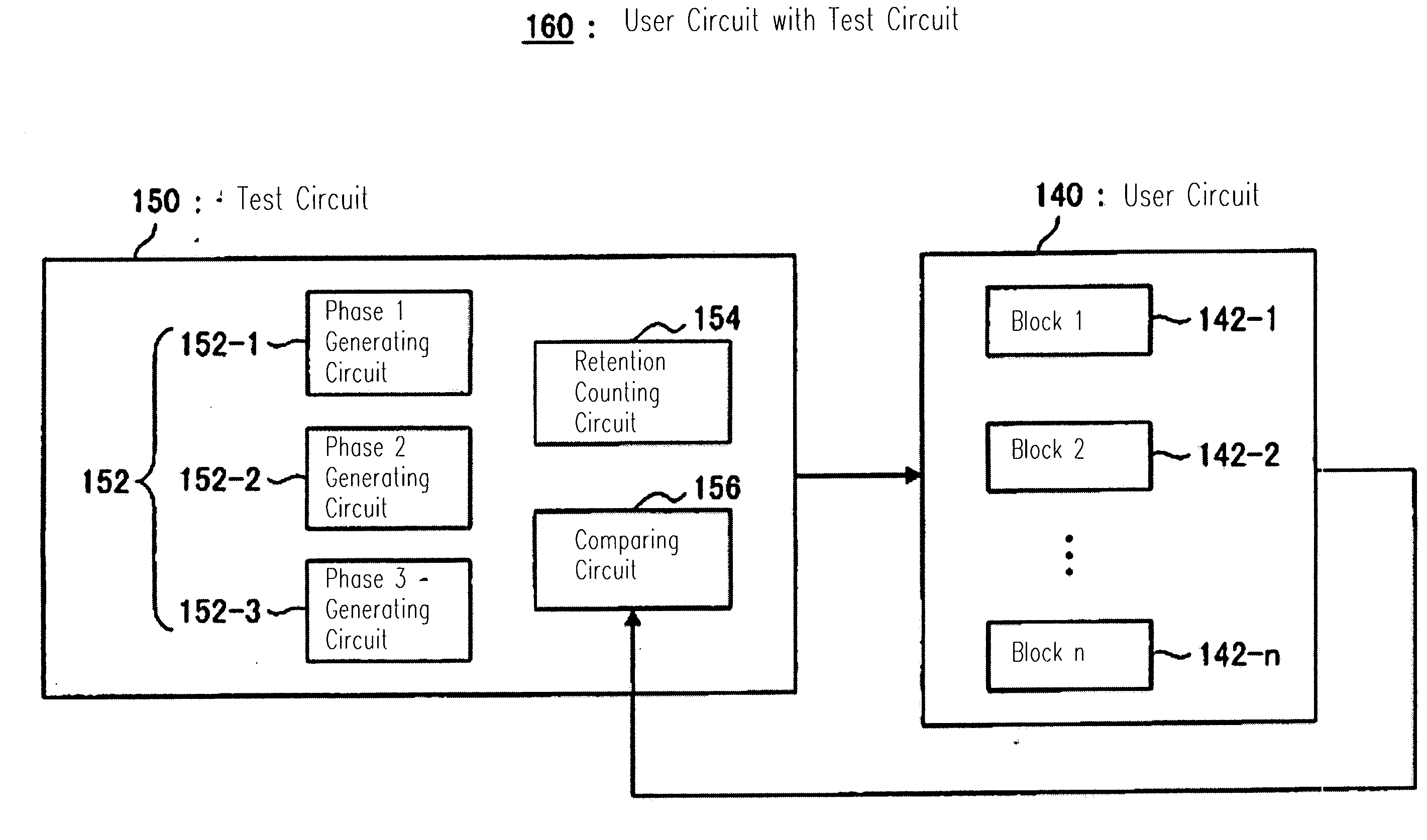
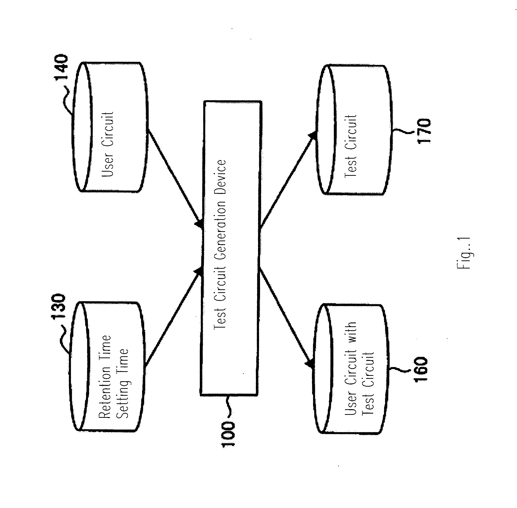
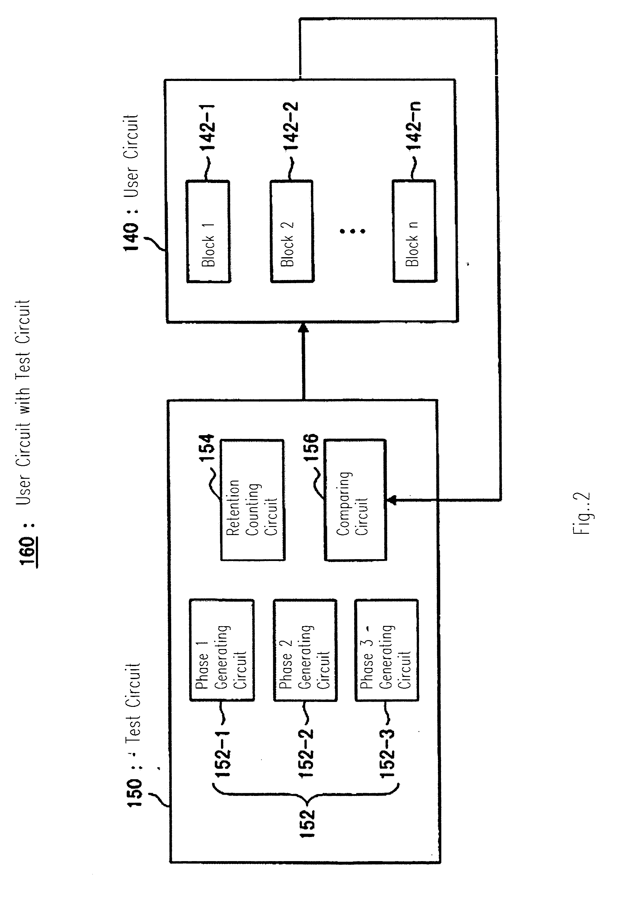
[0035] The preferred embodiments of the test method, the test circuit, and the test circuit building-in device according to the present invention will be explained in details as below, referring to the attached drawings. In the descriptions and the drawings of the invention, duplicate explanations are omitted by providing the elements having the identical functions and configurations with the same numerals.

[0036] According to the embodiment of the invention, the phase test of every block is done in serial, while the retention test of every block is conducted immediately after the phase test is completed. In other words, the feature is that the retention tests are carried out at the same time, being delayed. As the operations are only halted during the retention, no influence arises even when the retention test of every block is done at the same time.

[0037]FIG. 1 shows the explanatory drawing of a test circuit building-in device according to the preferred embodiment of the inventio...


PUM


Abstract

A test method includes starting a first phase test for a first block, starting a retention test for the first block shortly after the first phase test for the first block is over and starting a first phase test for a second block shortly after the first phase test for the first block is over.

Description

BACKGROUND OF THE INVENTION [0001] 1. Field of the Invention [0002] The present invention relates to test methods, test circuits, test circuit building-in devices, and computer programs. Especially, the present invention relates to test methods, test circuits, test circuit devices, and computer programs for shortening a test time when a retention test is done during testing a user circuit including a plural of circuits (blocks). The above mentioned retention test is a test for ascertaining whether a value is retained, or not, after turning off the operation of the user circuit for a certain period. Generally, the period of turning off the operation of the user circuit during the retention test is longer than the period of tests except the retention test (phase tests). [0003] 2. Description of the Related Art [0004] In tests procedures for LSI, an attempt is made to shorten the test time by simultaneous tests of every block, however, an voltage drop arises from an over peak-currency ...

Claims


Application Information

Patent Timeline
Patent Type & Authority Applications(United States)
IPC IPC(8): G06F3/00
CPCG01R31/31707
Inventor NOZAKI, YASUHIROUSHIKUBO, MASANORI
Owner OKI ELECTRIC IND CO LTD
Learn More