A and B glue dispenser

A technology of glue machine and glue point, which is applied in the direction of coating, surface coating liquid device, etc., can solve the problems of dispensing, lower production efficiency, deformation of valve channel and valve port, etc., to save replacement time and positioning Time, improve production efficiency, increase the effect of service life

Inactive Publication Date: 2016-03-09
KUNSHAN XUNTAO PRECISION MACHINERY
View PDF6 Cites 28 Cited by
  • Summary
  • Abstract
  • Description
  • Claims
  • Application Information

AI Technical Summary

Problems solved by technology

[0004] At present, there are various dispensing machines with different functions on the market, but as far as AB dispensing machines are concerned, most of the existing dispensing machines have the following disadvantages: (1). Generally, glue tubes below 300ml are used for incoming glue Packaging, mass production requires frequent replacement of hoses, which cannot achieve continuous dispensing, resulting in low production efficiency
(2). The glue mixing ratio should be determined according to the diameter of the incoming rubber hose, and it cannot be combined at will.
(3). It is known that the valve body is mostly made of PP material. When the temperature of the glue rises, the valve body will expand with heat and contract with cold, resulting in more deformation of the valve channel and the valve port, and because most of the pneumatic controllers cannot be well The control of the glue flow rate greatly reduces the dispensing accuracy
[0005] The existing dispensing machine needs to reposition the needle when replacing the dispensing needle and the mixing tube, which takes a long time and reduces production efficiency
[0006] In view of the above reasons, the existing dispensing machine cannot meet the requirements of mass production, high efficiency, high quality and fast assembly production, so it is necessary to develop a new AB glue dispensing machine

Method used


Image

  • A and B glue dispenser
  • A and B glue dispenser
  • A and B glue dispenser

Examples


Embodiment Construction

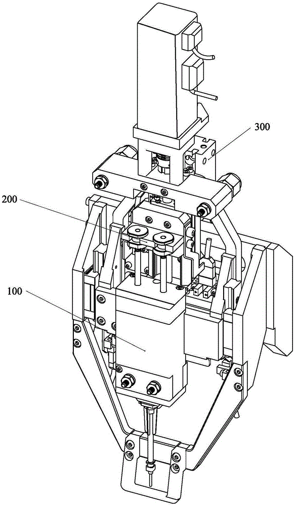
[0019] refer to Figure 1 to Figure 6 As shown, the AB glue dispensing machine of the present invention is composed of a set of plunger type glue dispensing valve 100, a set of mechanism 200 for precisely controlling the amount of glue, and a set of mechanism 300 for quickly replacing the mixing tube and needle.

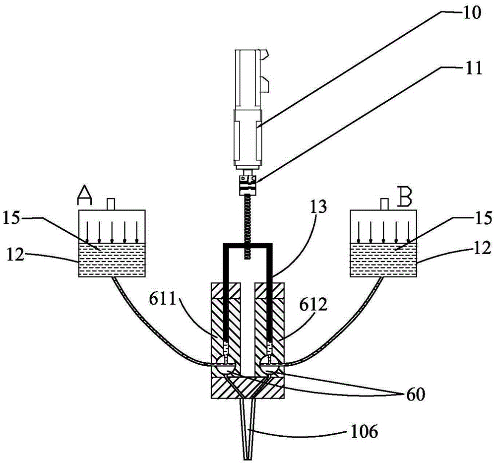
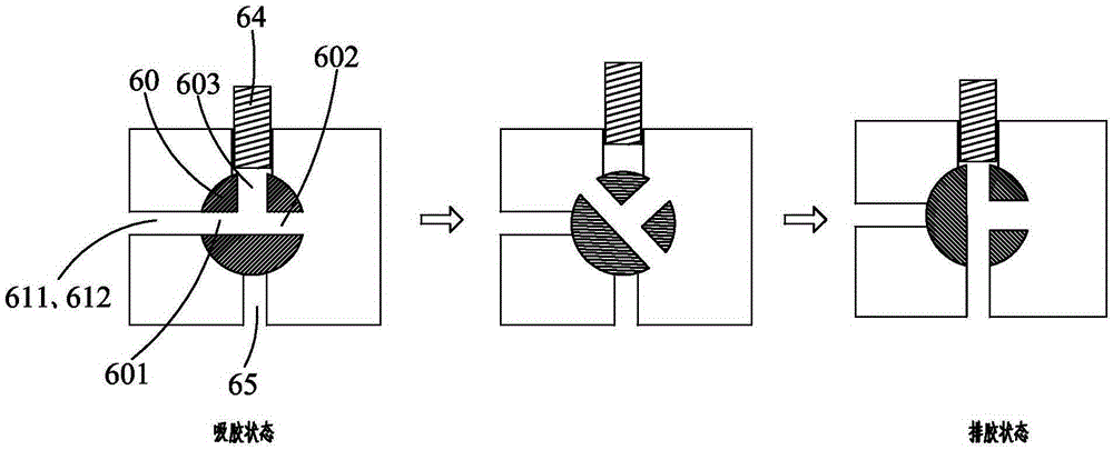
[0020] The plunger type glue dispensing valve 100 includes two separately separated cavities, respectively A glue temporary storage cavity 611 and B glue temporary storage cavity 612, each cavity has a rotary switch valve 60, and the switch valve 60 is provided with a glue inlet 601, a glue outlet 602 and an air filling port 603 that are connected to each other. At the glue port 602, the two switching valves 60 rotate simultaneously to switch.

[0021] The plunger type dispensing valve 100 has two working states, which are the glue feeding state and the glue discharging (glue dispensing) state. In the glue feeding state: the two rotary switching valves 60 correspon...


PUM


Abstract

The invention discloses an A and B glue dispenser. The A and B glue dispenser comprises a set of plunger type glue dispensing valve feeding and discharging A and B glue continuously, a set of glue pushing mechanism precisely controlling glue amount and a set of mechanism capable of rapidly replacing glue mixing pipes and a glue dispensing needle head. Different mixing proportions of the A and B glue can be obtained by changing the diameter of a piston rod through the plunger type glue dispensing valve. The plunger type glue dispensing valve can be connected with big glue barrels and continuous glue dispensing is achieved without changing glue pipes. The glue pushing mechanism drives a lead screw to push a piston through a stepping or servo motor, and precise glue ranking control is achieved. When the glue mixing pipes and the glue dispensing needle head need to be replaced, the needle head replacing mechanism can separate the glue mixing pipes from the needle head, and the needle head position after replacement is not needed to be recalibrated.

Description

technical field [0001] The invention relates to an AB glue dispensing machine, in particular to an AB glue dispensing machine capable of continuous glue dispensing and precise control of glue output. Background technique [0002] With the rapid development of 3C products such as automotive electronics and consumer electronics, the types and quantities of the corresponding products are increasing day by day. high demands. [0003] AB type glue, also known as two-component glue, is widely used for filling and sealing of products due to its excellent bonding strength and good storage performance. [0004] At present, there are various dispensing machines with different functions on the market, but as far as AB dispensing machines are concerned, most of the existing dispensing machines have the following disadvantages: (1). Generally, glue tubes below 300ml are used for incoming glue Packaging and mass production require frequent replacement of hoses, which cannot achieve cont...

Claims


Application Information

Patent Timeline
Patent Type & Authority Applications(China)
IPC IPC(8): B05C5/02B05C11/10
Inventor 顾福乾
Owner KUNSHAN XUNTAO PRECISION MACHINERY
Why Eureka
Try Eureka