Direction-turning device for the lens of a camera phone

Inactive Publication Date: 2006-11-23
HWANG JIN CHYUAN
2 Cites 76 Cited by

AI-Extracted Technical Summary

Problems solved by technology

But, if a user wants to take a self-shooting picture, he has to stand in front of a mirror and keep the lens aimed at the portrait in the mirror for...

Benefits of technology

[0008] The main characteristics of the invention contained in a groove cut in an edge at the rear side of the camera phone are a lens base, a positioning unit, a driving unit and a restricting unit. The lens base fitted in the groove is provided with a pivot at two sides respectively connected pivotally in an interior wall of the groove. The driving unit is able to activate the pivot to rotate for 180 degrees. And, because the driving unit and the pivot of the lens base are linked only by viscous oil, so the lens base can also be...

Abstract

A direction-turning device for the lens of a camera phone contained in the rear side of the camera phone includes a lens base having a pivot at two sides respectively connected pivotally in an interior wall of the groove, a driving unit able to rotate the pivot for 180 degrees, and a positioning unit having an auxiliary gear fixed with the lens base and an elastic locking wire always stopping the auxiliary gear to keep the lens base positioned stably when moved to a position electronically or manually. The driving unit and the pivot of the lens base are linked by viscous oil, enabling the lens base driven by the driving unit or manually. The invention is totally hidden to keep the camera phone looked normally and able to shift the lens to face forward or backward with a self-shooting function.

Application Domain

Television system detailsInterconnection arrangements +10

Technology Topic

Camera lensUnit/actuation +2

Image

  • Direction-turning device for the lens of a camera phone
  • Direction-turning device for the lens of a camera phone
  • Direction-turning device for the lens of a camera phone

Examples

  • Experimental program(1)

Example

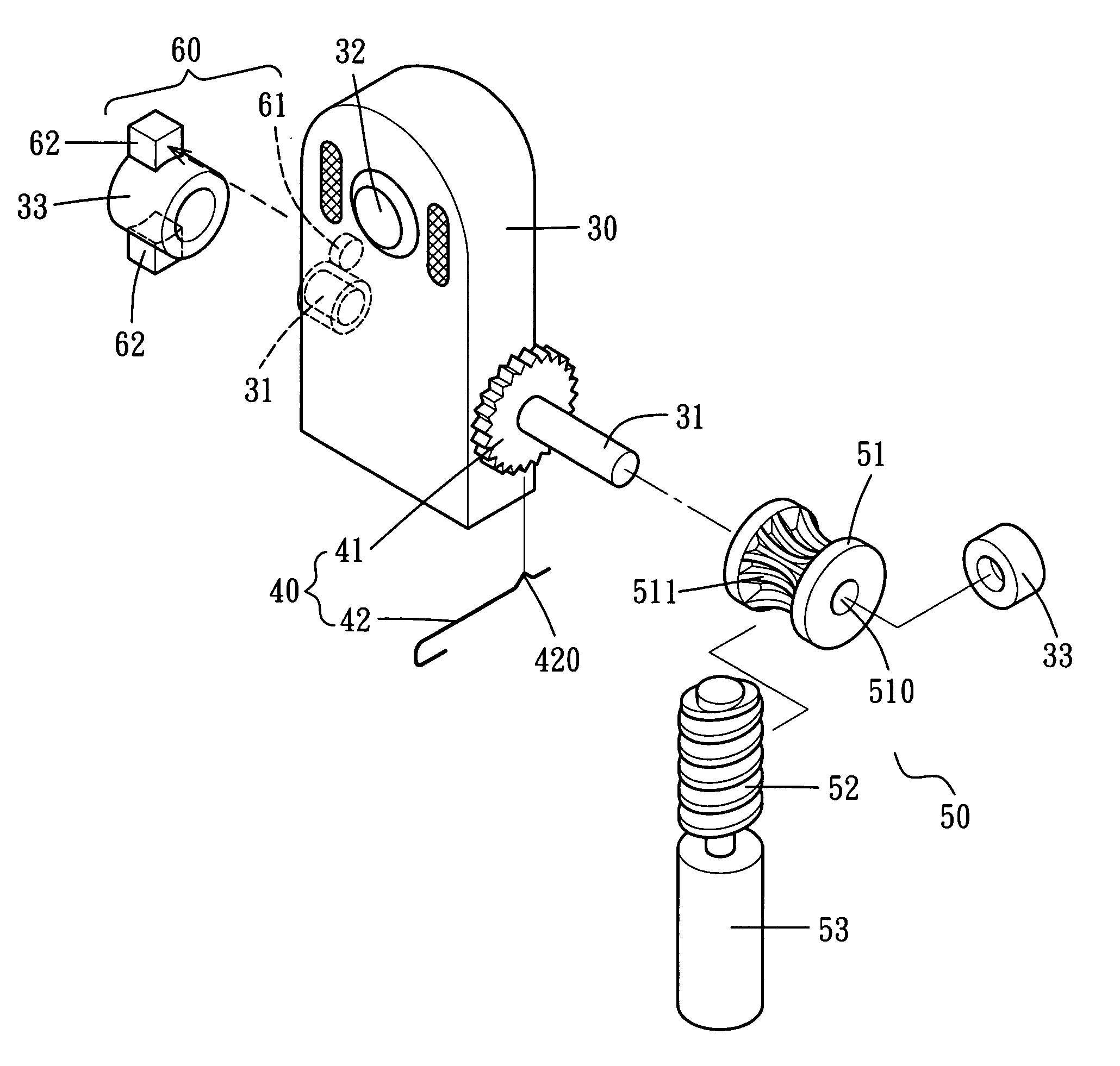
[0026] As shown in FIGS. 5, 6 and 7, a first preferred embodiment of a direction-turning device for the lens of a camera phone 20 in the present invention includes a lens base 30, a positioning unit 40, a driving unit 50 and a restricting unit 60. The camera phone 20 is provided with a groove 21 cut in the central top portion of the rear side.
[0027] The lens base 30 having exactly the same shape and size as the groove 21 for being fitted in the groove 21 is provided with a pivot 31 extended outwards eccentrically at two sides respectively and fitted in a pivot hole in the interior wall of the groove 21, a lens 32 located in the rear side and two supporting members 33 respectively used to support one end of each pivot 31.
[0028] The positioning unit 40 is provided with an auxiliary gear 41 fixed together with a sidewall of the lens base 30 (or able to be formed together integral) and an elastic locking wire 42 (able to be formed by bending a steel wire) provided with a conical hump 420 that is protruded toward the auxiliary gear 41 to fit in a gap between two teeth of the auxiliary gear 41, as shown in FIGS. 7 and 9.
[0029] The driving unit 50, as shown in FIGS. 6 and 7, able to be controlled by a button on the phone is provided with a worm gear 51 having a hole 510 at the center for one of the pivots 31 of the lens base 30 to insert and worm teeth 511 for engaging with a worm 52 driven by a motor 53 to rotate. Then, viscous oil is filled in between the pivot 31 and the hole 511.
[0030] The restricting unit 60, as shown in FIG. 6, used to control the displacement of the lens base 30 is provided with a first sensor 61 fixed at one side of the lens base 30 and two second sensors 62 set on the outer edge of the supporting member 33 spaced apart oppositely, as shown in FIGS. 6 and 7, and able to be moved to align with the first sensor 61 for stopping the motor 53 of the driving unit 50 from rotating. And, if the restricting unit 60 is not controlled electronically, it can be replaced with a blocking device to do the job.
[0031] In using, as shown in FIG. 6, the operating procedures are described as below.
[0032] 1. For a self-shooting usage: Press the controlling button to start activating the motor 53 of the driving unit 50 to enable the worm 52 and the worm gear 51 to rotate successively. Because of the viscous oil filled between the hole 510 of the worm gear 51 and the pivot 31 of the lens base 30, the pivot 31 is to be moved to spin when the worm gear 51 is driven to reach a certain speed, so is the lens base 30 to be turned upwards for 180 degrees by means of the pivot 31 of the lens base 30, until the lens base 30 stands vertically, as shown in FIGS. 9 and 10. By the time, the first sensor 61 and one of the second sensors 62 are aligned to cease the motor 53, enabling the lens 32 in the lens base 30 to face toward the front side of the phone instead of the rear side originally, as shown in FIGS. 6, 9 and 10, ready for a user to shoot himself (herself). In addition, because the worm gear 51 and the lens base 30 are linked only by viscous ;oil, not immovable, the lens base 30 can also be moved manually as long as a user exerts force surpassing a sticky resistance caused by the viscous oil. Moreover, since the auxiliary gear 41 is always locked by the conical hump 420 of the elastic locking wire 42, the lens base 30 is any time positioned stably whenever it stands quietly or is being moved.
[0033] 2. For a normal usage: First, press the controlling button to start activating the driving unit 50 to turn the lens base 30 back in the groove 21 or do it manually, as shown in FIG. 11. By the time, the lens 32 is facing in a direction as the rear side of the camera phone 20 is, ready for normal shooting.
[0034] Next, as shown in FIGS. 12 and 13, a second preferred embodiment of a direction-turning device for the lens of a camera phone in the present invention has mostly the same components as the first embodiment does. The different parts are described below. The part of the pivot 31 fitting tightly in the hole 510 of the worm gear 51 is shaped rounded and that between the worm gear 51 and the auxiliary gear 41 is shaped polygonal, such as hexagonal. And, a coiled spring 54 and a geared disc 55 to be matched with the worm gear 51 are engaged with the polygonal part of the pivot 31 and located between the auxiliary gear 41 and the worm gear 51. The geared disc 55 is provided with gear teeth 550 for engaging with gear teeth 520 formed on one side of the worm gear 51, as shown in FIG. 13. In case that the viscous oil filled between the pivot 31 and the worm gear 51 becomes degraded after a period of time, the coiled spring 54 can still expand to squeeze the gear dish 55 to closely match with the worm gear 51 so that the geared disc 55 is able to be driven to activate the pivot 31 to rotate and the lens base 30 is of course to be moved without difficulty. And, similar to the first embodiment, the lens base 30 is any time positioned stably regardless of standing immoably or being moved, since the auxiliary gear 41 is always locked by the conical hump 420 of the elastic locking wire 42.
[0035] In addition, as shown in FIGS. 14-16, the groove 21 for containing the lens base 30 can also be cut on one side of the camera phone 20.
[0036] The invention has the following advantages as can be seen from the foresaid description.
[0037] 1. The lens base 30 carrying the lens 32 is hidden in the rear portion of the camera phone 20, keeping the front side of the camera phone 20 unaffected wholly and aesthetically.
[0038] 2. The lens 32 (the lens base 30) can be controlled electronically or manually to change its direction.
[0039] 3. The lens 32 (the lens base 30) can be positioned stably by the positioning member 40 while it is being moved to change direction.
[0040] While the preferred embodiment of the invention has been described above, it will be recognized and understood that various modifications may be made therein and the appended claims are intended to cover all such modifications that may fall within the spirit and scope of the invention.

PUM

no PUM

Description & Claims & Application Information

We can also present the details of the Description, Claims and Application information to help users get a comprehensive understanding of the technical details of the patent, such as background art, summary of invention, brief description of drawings, description of embodiments, and other original content. On the other hand, users can also determine the specific scope of protection of the technology through the list of claims; as well as understand the changes in the life cycle of the technology with the presentation of the patent timeline. Login to view more.
Why Eureka
Try Eureka