Offshore power generator with current, wave or alternative generators

a technology of generators and offshore oil platforms, applied in the direction of electric generator control, machines/engines, mechanical equipment, etc., can solve the problem that none of the above inventions provides a re-usable offshore oil platform for providing an alternative energy sour

Active Publication Date: 2006-11-23
GEHRING DONALD HOLLIS
View PDF22 Cites 73 Cited by
  • Summary
  • Abstract
  • Description
  • Claims
  • Application Information

AI Technical Summary

Problems solved by technology

Oil companies routinely pay millions of dollars to have the platforms removed and the platforms often become the property of the remover.
None of the above inventions provide a re-usable offshore oil platform to provide an alternative energy source.

Method used


Image

  • Offshore power generator with current, wave or alternative generators
  • Offshore power generator with current, wave or alternative generators
  • Offshore power generator with current, wave or alternative generators

Examples


Embodiment Construction

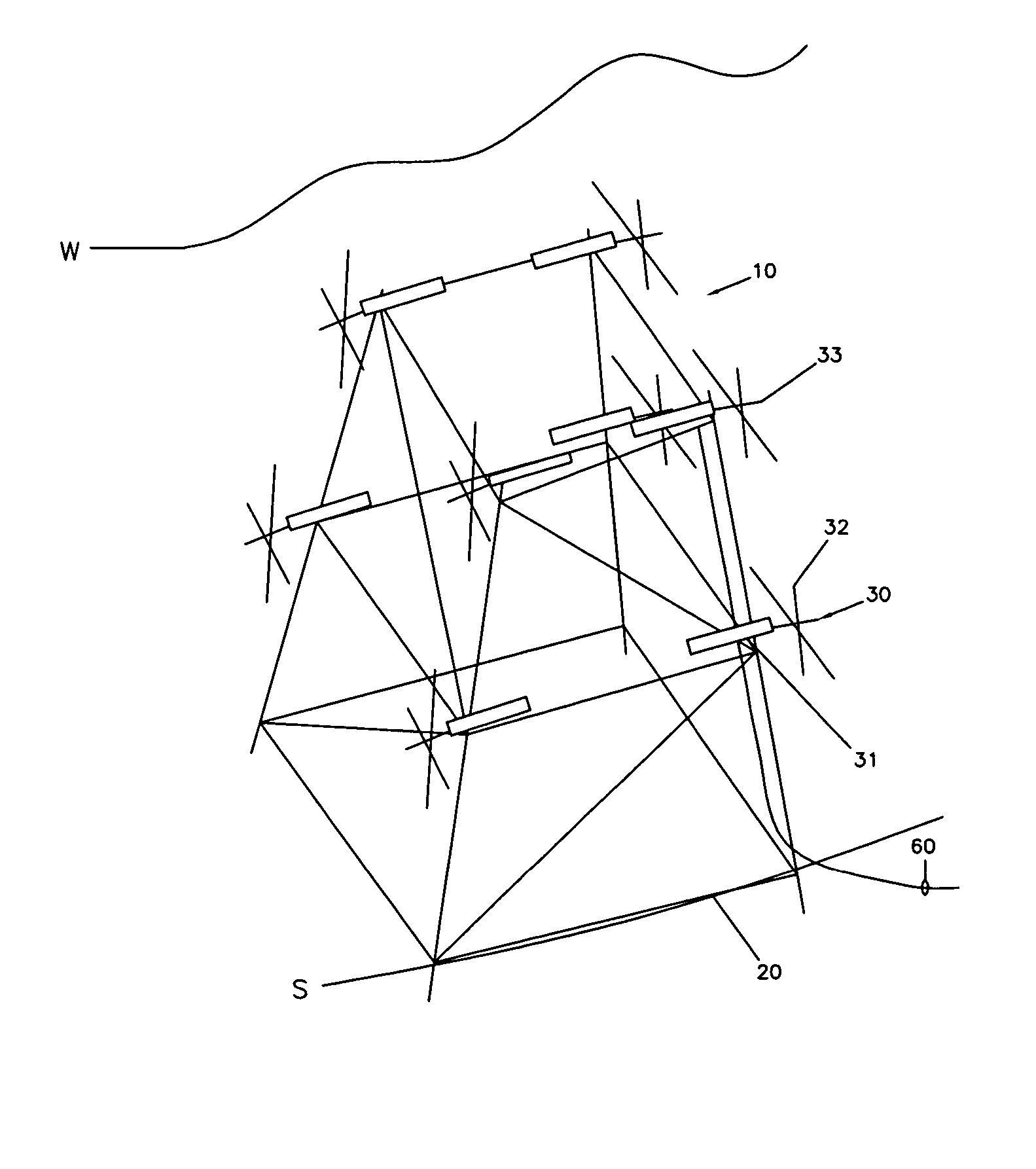
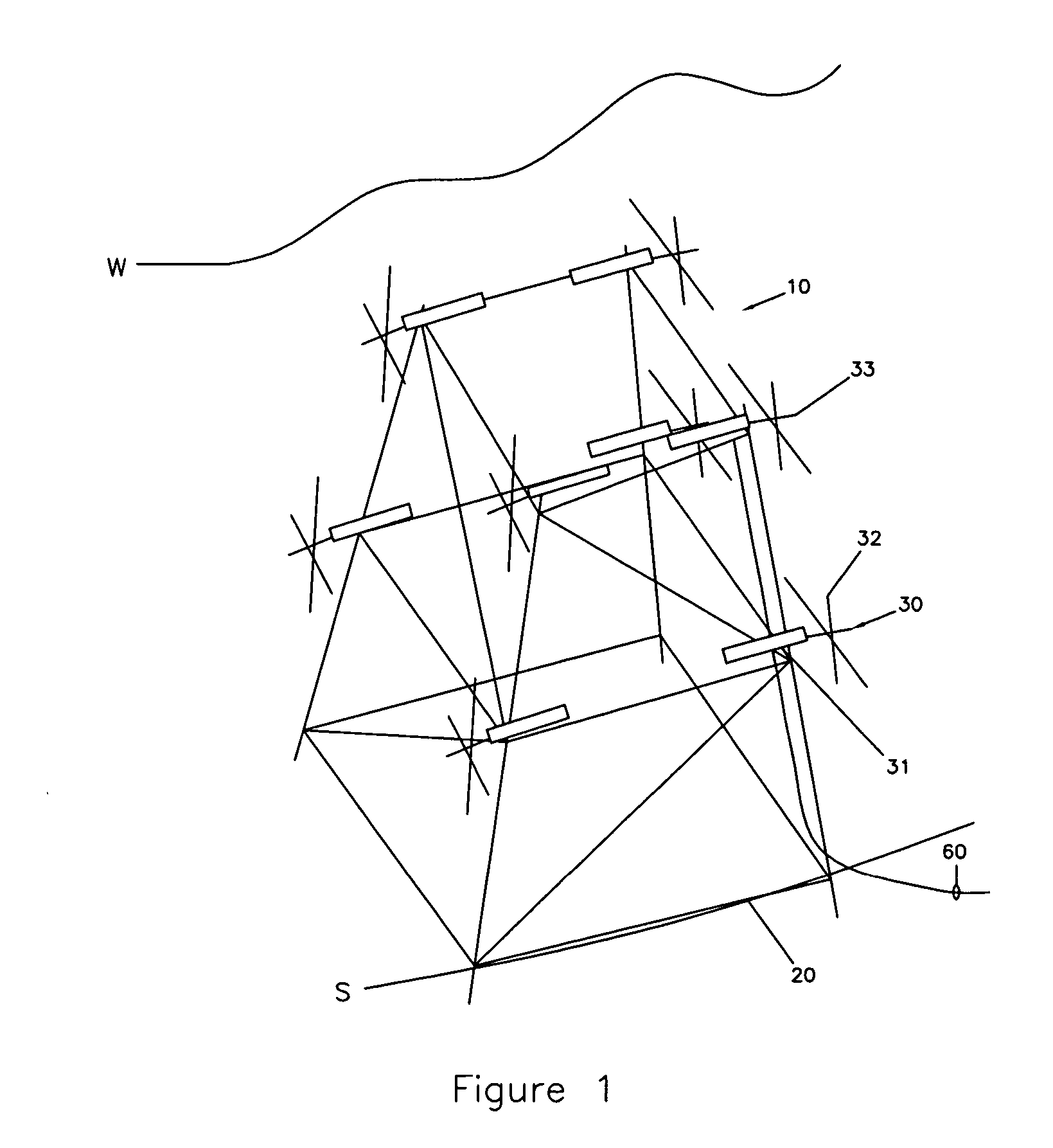
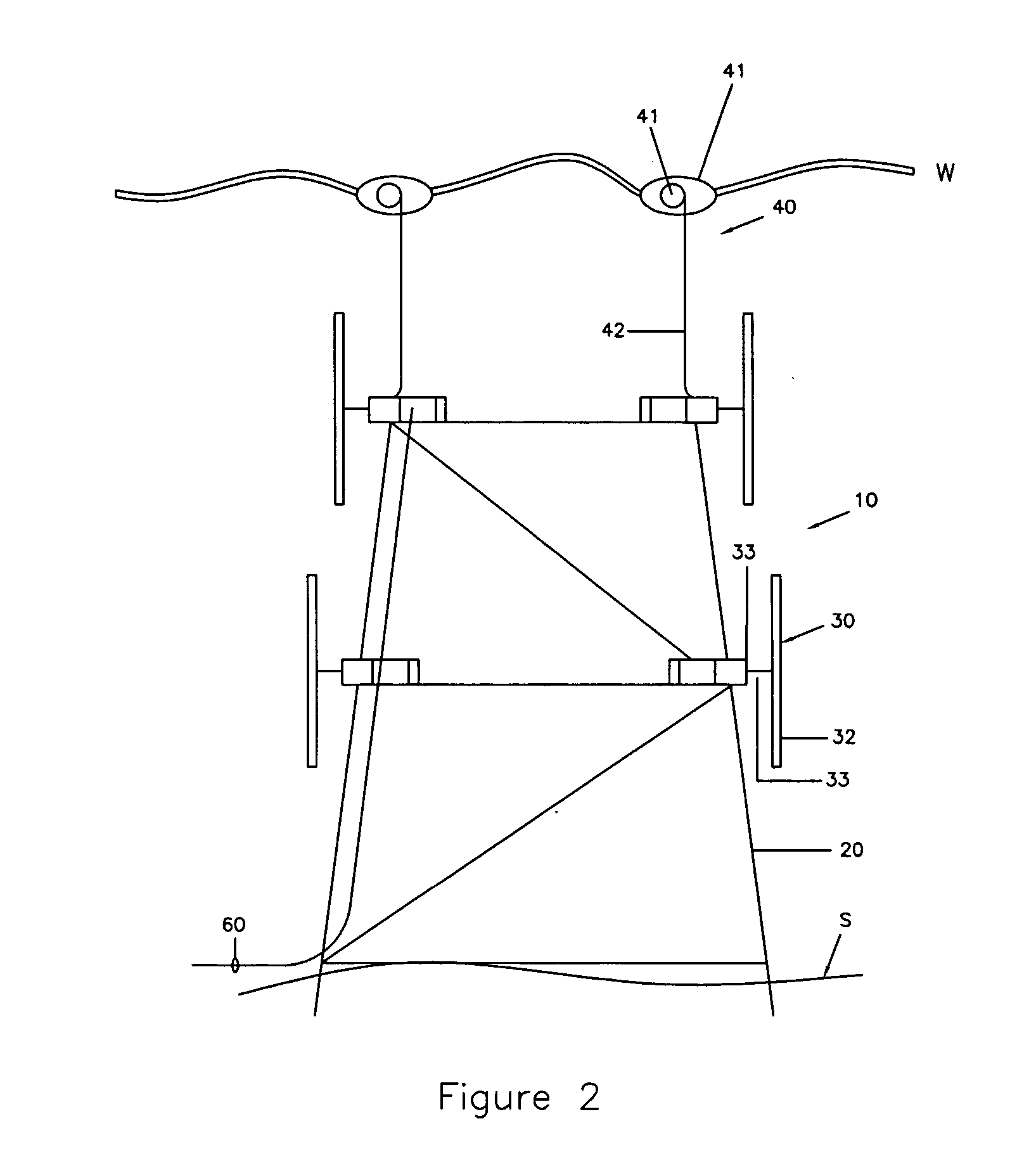
[0034] Referring now to the drawings, wherein like reference numerals refer to the same components across the several views and in particular to FIGS. 1, 2, and 3, there is shown an offshore power generator 10. The offshore power generator 10 includes an offshore platform 20 and current generators 30.

[0035] The offshore platform 20 rests on the seabed S and has mounted on it a plurality of generators 30. Each current generator 30 in this embodiment of the present invention includes a generator 31, a shaft 33 rotatably mounted within and protruding out of the generator 31, and a plurality of blades 32 mounted to the shaft 33 to turn the shaft 33 in response to water current flow. Electrically connected to the current generators 30 are power cables 60. The power cables 60 transmit the energy generated by the current generators 30 for consumption. For example, the power cables 60 may be connected to a power grid G, located onshore.

[0036] Referring now to FIG. 2, the offshore power ge...


PUM


Abstract

An offshore power generator is disclosed. The offshore power generator includes an offshore platform, which can be a new, existing, abandoned, removed, dumped or relocated fixed or floating offshore platform; one or more types of current, wind, wave and other renewable energy generators mounted to the offshore platform; and interconnecting power cables, in electrical communication with the current generators for distribution from the generators to end users.

Description

CROSS REFERENCED TO RELATED APPLICATIONS [0001] This application is a continuation in part of U.S. application Ser. No. 11 / 132,489 “Current Power Generator” filed on May 19, 2005 which is incorporated herein in its entirety. This application is also a continuation in part of U.S. application Ser. No. 11 / 142,145 “Ocean Wave Generator” filed Jun. 1, 2005 which is incorporated herein in its entirety.FIELD OF THE INVENTION [0002] The present invention relates to offshore platforms, and in particular to an offshore power generator using a new, existing, abandoned, removed, dumped or relocated fixed or floating offshore platform. BACKGROUND OF THE INVENTION [0003] Ordinarily, after an offshore platform has fulfilled its use by extracting all the oil or gas it can from a given location, it is merely discarded. Typically, the platforms are removed to 15 feet below the mudline. Oil companies routinely pay millions of dollars to have the platforms removed and the platforms often become the pr...

Claims


Application Information

Patent Timeline
Patent Type & Authority Applications(United States)
IPC IPC(8): F03D9/00H02P9/04
CPCE02B2017/0091Y02E10/728F03B13/1885F03B17/061F03D9/008F03D11/04F05B2240/40F05B2240/911F05B2240/93F05B2240/95Y02E10/22Y02E10/28Y02E10/38Y02E10/725Y02E10/727F03B13/10F03D13/25B63B2035/4466F03D9/255Y02E10/20Y02E10/30Y02E10/72
Inventor GEHRING, DONALD HOLLIS
Owner GEHRING DONALD HOLLIS
Why Eureka
Try Eureka