Optical radiation coupling module

a technology of optical radiation coupling module and coupling module, which is applied in the field of optical modules, can solve the problems of complex manufacturing cost, drawbacks and limitations of coupling efficacy, and achieve the effect of sufficient coupling efficacy, easy and cost-effective manufacturing

Inactive Publication Date: 2006-11-23
STMICROELECTRONICS SRL
View PDF6 Cites 17 Cited by
  • Summary
  • Abstract
  • Description
  • Claims
  • Application Information

AI Technical Summary

Benefits of technology

[0007] The present invention provides an optical module alternative to traditional ones to ensure sufficient coupling efficacy while at the same time being easy and cost-effective to manufacture. This is achieved by a module which includes a waveguide for the propagation of op

Problems solved by technology

The problem of providing optical structures that obtain a high coupling efficacy between an optoelectronic device (such as an optical radiation emitter or receiver) and a waveguide (such as an optical fibre) has been felt for a

Method used


Image

  • Optical radiation coupling module
  • Optical radiation coupling module
  • Optical radiation coupling module

Examples


Embodiment Construction

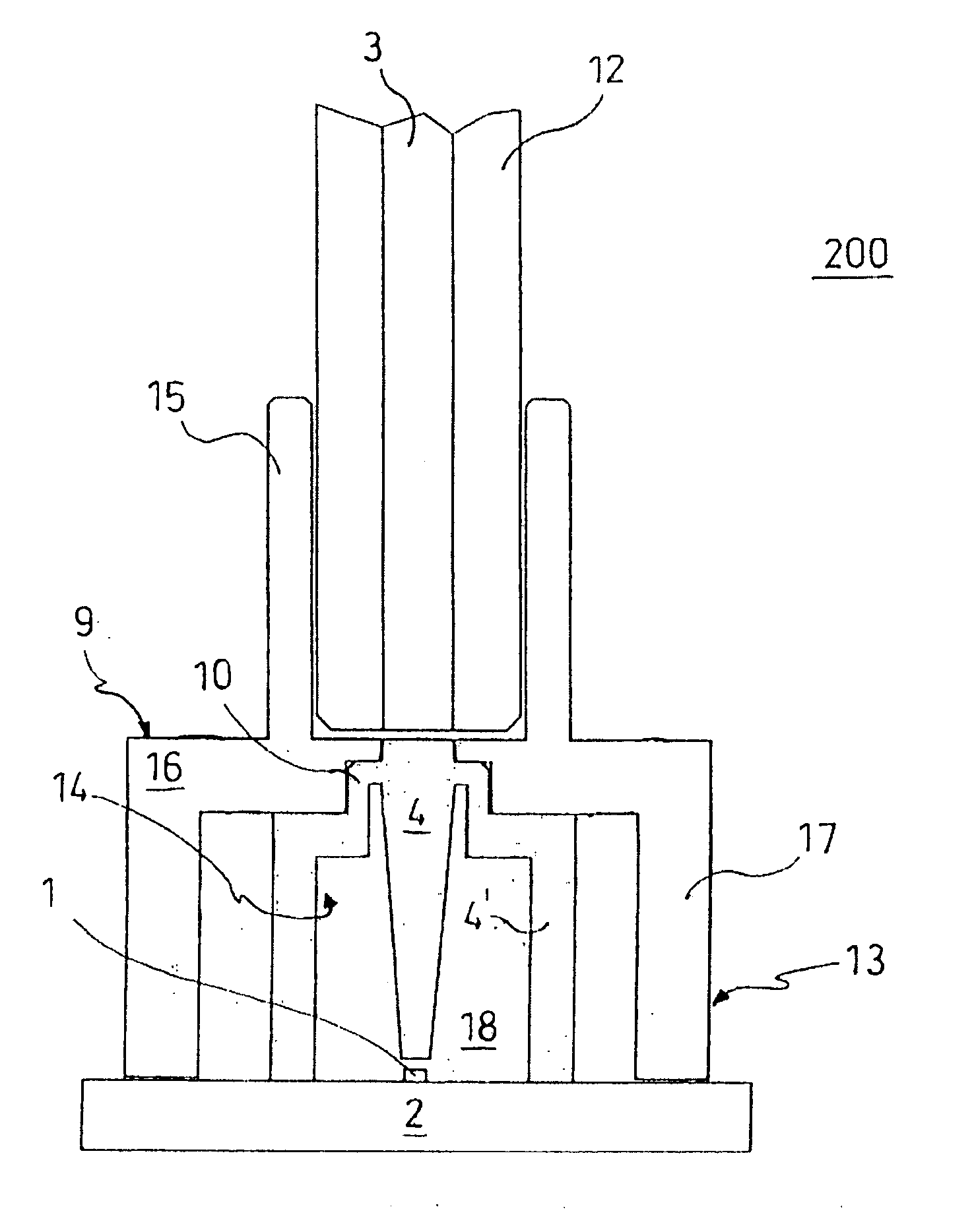
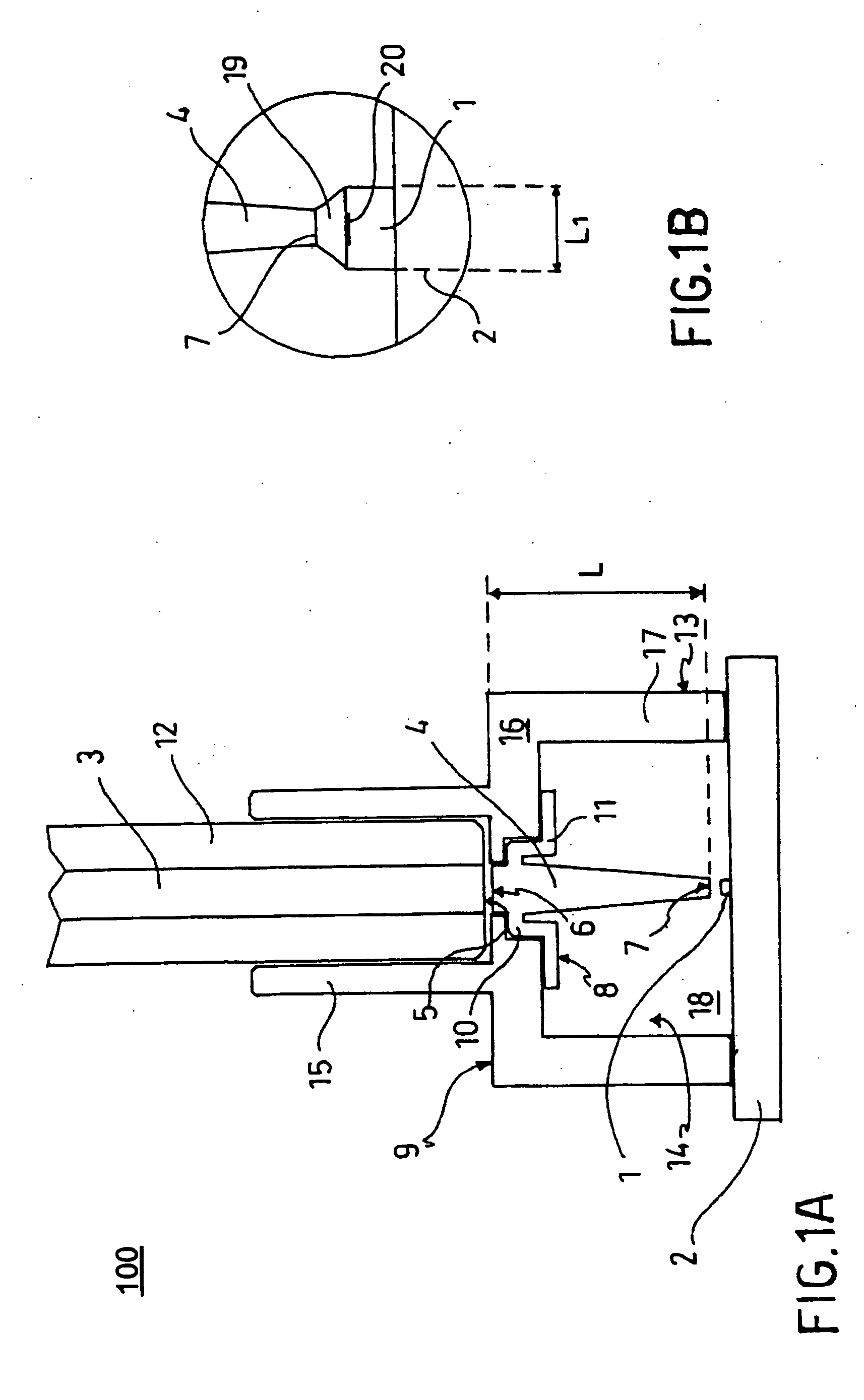
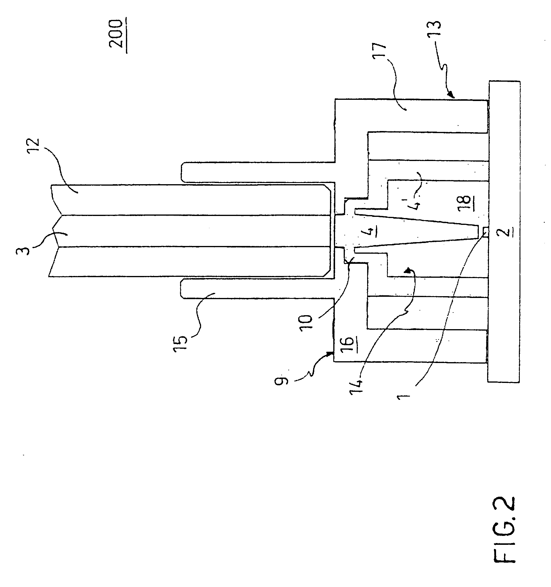
[0019]FIG. 1 illustrates a first optical module 100 provided according to a first exemplary embodiment of the invention. The optical module 100 includes an optoelectronic device 1 arranged on a substrate 2, a waveguide 3 for the propagation of optical radiation, and a guiding element 4 for coupling the waveguide 3 to the optoelectronic device 1.

[0020] Particularly, the optoelectronic device 1 can be an optical radiation transmitter employed in the field of optical communications. For example, in some embodiments, this transmitter is an LED diode (Light Emitting Diode) of the conventional type mounted on the substrate 1 such that it can emit radiation to the waveguide 3. Other examples of emitting optoelectronic devices useful in the inventive module are RCLED (Resonant Cavity Light Emitting Diode) or VCSEL (Vertical Cavity Surface Emitting Laser). Alternatively, the optoelectronic device 1 is a receiver useful in optical communications made, for example, with a conventional PIN pho...


PUM


Abstract

An optical radiation coupling module includes a waveguide for the propagation of optical radiation, an optoelectronic device arranged on a substrate, and a mechanism for coupling the radiation between the waveguide and the optoelectronic device. The coupling mechanism includes a guiding element moulded and tapered in a radiation propagation direction.

Description

RELATED APPLICATION [0001] The present application claims priority of European Patent Application No. 05425321.6 filed May 13, 2005, which is incorporated herein in its entirety by reference. FIELD OF THE INVENTION [0002] The present invention relates to an optical module for the coupling of optical radiation between an optoelectronic device and a waveguide. BACKGROUND OF THE INVENTION [0003] The problem of providing optical structures that obtain a high coupling efficacy between an optoelectronic device (such as an optical radiation emitter or receiver) and a waveguide (such as an optical fibre) has been felt for a long time. Particularly, there are applications such as optical communication requiring an LED (Light Emitting Diode) emitter or diode photo-detector PIN to be coupled with an optical fibre while minimizing the scattered optical power. [0004] To this end, U.S. Patent Publ. No. 2004 / 0008952A describes a coupling device which includes an LED diode fixed on a substrate and ...

Claims


Application Information

Patent Timeline
IPC IPC(8): G02B6/26
CPCG02B6/4201G02B6/4204G02B6/4249G02B6/4246G02B6/423
Inventor FINCATO, ANTONIOBARGE, DANIELACHIARETTI, GUIDO
Owner STMICROELECTRONICS SRL
Why Eureka
Try Eureka