Method for manufacturing open porous components of metal, plastic or ceramic with orderly foam lattice structure

a technology of foam lattice structure and open porous components, which is applied in the direction of manufacturing tools, foundry patterns, foundry moulding apparatus, etc., can solve the problems of difficult to clearly define the mechanical properties of the component cannot be clearly defined with difficulty, and the different size of the bubbles that develop

Inactive Publication Date: 2009-09-15
KURTZ +2
View PDF9 Cites 19 Cited by
  • Summary
  • Abstract
  • Description
  • Claims
  • Application Information

AI Technical Summary

Benefits of technology

[0010]As a matter of principle, the method for manufacturing the individual core lattice planes can be performed in any way. It has proved to be particularly advantageous to shape the individual core lattice planes in a first operation through joining the core bodies into plates that are fixed planar, bent or curved in any way. Only by stacking the individual core lattice planes on top of one another, more preferably of the plates that constitute them, a desired shape of the core lattice is created. Through such a layer-by-layer construction it is advantageously possible to manufacture the core lattice independently and after the manufacture of the individual core lattice planes, more preferably it is conceivable to pre-fabricate core lattice planes, cut them in a desired shape if required and assemble them into a core lattice. This enables favorable, rational and quick manufacture of the core lattice from prefabricated core lattice planes, more preferably of prefabricated plates.
[0013]The method for manufacture of the individual core lattice planes can be embodied in any way. The bodies within the core lattice structure however have a defined size, for example 10 mm and can be manufactured in a lattice network. Here, a suitable foundry core sand can be mixed with a known core sand binder for example and this core lattice plane base material formed and cured through a suitable core manufacturing method. To manufacture the individual core lattice planes it is particularly advantageous here that known betaset, coldbox, hotbox or croning methods with organic binder components are used. With these known methods for the manufacture of casting molds the core lattice planes can be manufactured cost-effectively and easily without special conversion of the casting process.
[0014]In the process it is particularly favorable if in the manufacture of the core lattice planes, water-soluble inorganic binder components based on magnesium sulphate, phosphate or silicate or a mixture of these are used. These inorganic binders are excellently suitable in a cost-effective and simple way to manufacture sturdy core lattice planes that can be assembled into complex core stacks.
[0015]The material which is used for constructing the individual core lattice planes can, as a matter of principle, be randomly selected from the range of the materials that are conventionally used for inner casting molds. However it has preferably shown that inorganic powder or sands, more preferably consisting of quartz, feldspar, aluminum oxide, refractory, olivine, chromium ore, clay, fluorspar, silicate or bentonite or a mixture of these, are suitable for the manufacture of core lattice planes. From these materials core bodies can be manufactured in a particularly easy way and combined with the above-mentioned core sand binders so that particularly durable and easily processable core lattice planes can be manufactured.
[0020]To accelerate the manufacturing speed and effectiveness in the manufacture of the core lattice it has proved to be particularly advantageous if at least two robots work in a cycle, wherein a robot works in the core manufacturing tool for the core manufacture, while the second robot performs the smoothing, assembling and placing of the core lattice. As a result it is possible that a core lattice plane is simultaneously manufactured through a robot while outside the core manufacturing tool, a second robot assembles, slicks and places already manufactured core lattice planes. Thus, a maximum work effectiveness and productivity in the manufacture of the core stack is provided.

Problems solved by technology

These known methods however have the disadvantage that through the injection of the gasses during the foaming-up process, bubbles develop which reach different, not clearly definable or foreseeable or desirable sizes.
Thus, components are created by means of these methods which have mechanical properties that can only be assessed with difficulty.
In this case, too, a clear definition of the mechanical properties of the component is impossible because of the unpredictability of the disorderly lattice structure in the interior of the components.

Method used


Image

  • Method for manufacturing open porous components of metal, plastic or ceramic with orderly foam lattice structure
  • Method for manufacturing open porous components of metal, plastic or ceramic with orderly foam lattice structure
  • Method for manufacturing open porous components of metal, plastic or ceramic with orderly foam lattice structure

Examples


Embodiment Construction

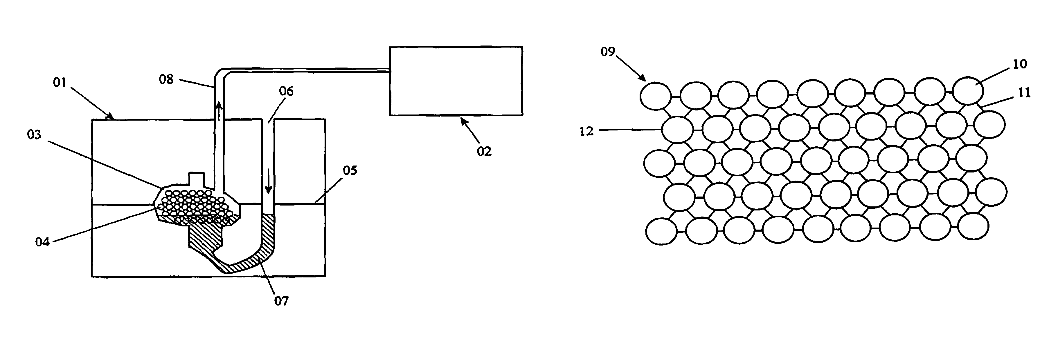
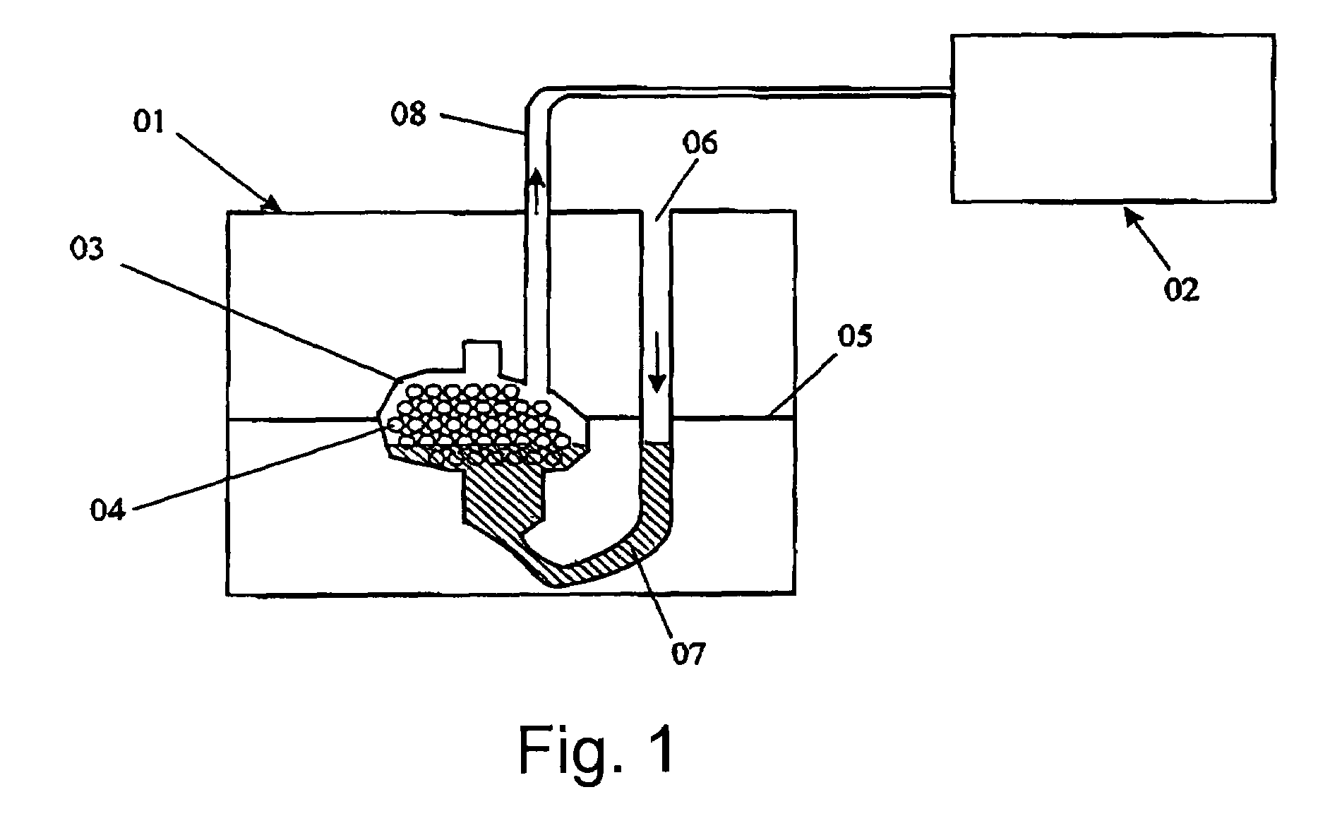
[0030]A casting device 01 is schematically shown in FIG. 1 in which a casting mold 03 is contained. In the casting mold 03, liquid material from an oven can be filled through a casting feed 06, wherein the liquid material forms a casting sump 07. Here, the liquid material flows into the casting mold 03 up to the level of the static pressure of the casting mold 07. The casting device 01 is constructed so that the casting mold 03 can be split at a splitting joint 05 in order to remove the cast component from the casting mold 03. In the interior of the casting mold 03 is located a core stack 04 which consists of individual core lattice planes which are assembled of individual core bodies and forms a regular core lattice. With the help of a vacuum station 02 a vacuum is created in the interior of the casting mold 03 through a vacuum discharge 06 so that the liquid material is drawn up within the core stack 04 in order to fill out the entire casting mold 03.

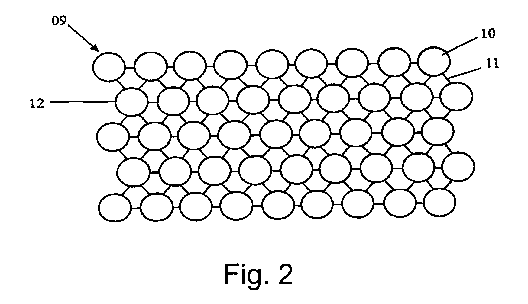
[0031]FIG. 2 shows a schematic...


PUM

PropertyMeasurementUnit
diameteraaaaaaaaaa
diameteraaaaaaaaaa
sizeaaaaaaaaaa

Abstract

The invention relates to a method for the manufacture of light open porous components of metal, metal alloys, plastic or ceramic of any geometry. Here, the component is produced through casting liquid material into a casting device (01), wherein a core stack (04) is mounted, cast and removed in a casting mold (03). The core stack (04) here is designed as a regular multi-dimensional core lattice (09) with defined core lattice planes (12), where each core lattice plane (12) is constructed of individual regular core bodies (10).

Description

CROSS-REFERENCE TO RELATED APPLICATIONS[0001]The present patent application claims priority from German Patent Application No. 10 2006 017 104.7, filed on Apr. 10, 2006.BACKGROUND OF THE INVENTION[0002]The invention relates to a method for manufacturing open porous light components of metal, metal alloys, plastic or ceramic of any geometry according to the teaching of claim 1.[0003]For manufacturing components of high strength and stiffness with low densities, methods are known from the prior art where metals are foamed-up in the liquid state with suitable foaming agents, e.g. gases, to manufacture components with the above-mentioned characteristics. These known methods however have the disadvantage that through the injection of the gasses during the foaming-up process, bubbles develop which reach different, not clearly definable or foreseeable or desirable sizes. Thus, components are created by means of these methods which have mechanical properties that can only be assessed with d...

Claims


Application Information

Patent Timeline
Patent Type & Authority Patents(United States)
IPC IPC(8): B22D19/00B22D29/00
CPCB22C9/10B22C9/105B22D25/005C22C1/08B22D19/14C22C2001/081C22C1/081
Inventor MUNZ, ULRICHKUHS, BERNDSTRUB, RAIMUND
Owner KURTZ
Why Eureka
Try Eureka