Planar diaphragm loudspeaker and related methods

a loudspeaker and diaphragm technology, applied in the direction of transducer diaphragms, electrical apparatus casings/cabinets/drawers, instruments, etc., can solve the problems of narrowing the application of acoustically transparent fabrics, limiting the advantage of the product, and disrupting the continuity of the ceiling surfa

Active Publication Date: 2005-08-16
AUDIO TECH ASSOC
View PDF48 Cites 18 Cited by
  • Summary
  • Abstract
  • Description
  • Claims
  • Application Information

AI Technical Summary

Benefits of technology

[0013]For purposes of summarizing the invention and the advantages achieved over the prior art, certain advantages of the invention have been described herein above. Of course, it is to be understood that not necessarily all such advantages may be achieved in accordance with any particular embodimen...

Problems solved by technology

Such grille is often perceived as visually unpleasant and also disrupts the continuity of the ceiling surface.
A recent interpretation of the latter is found in U.S. Pat. No. 6,386,315 issued to Kenneth P. Roy et al., though the fabric is stretched in front of the diaphragm but not in contact with its surface, therefore narrowing the application to acoustically transparent fabrics and therefore limiting its advantage.
Although the surface finishes abovementioned have been used in commerce, they are limited to a two-dimensional representation of a three-dimensional surface, which in many cases is not completely adequate or, even more, not substantially similar to the surrounding surface of the ceiling where the loudspeaker is intended to be installed.
Although it could be considered as an improvement over two-dimensional methods previously cited, the added mass and rigidity of such sheet and the lamination effect caused by the...

Method used


Image

  • Planar diaphragm loudspeaker and related methods
  • Planar diaphragm loudspeaker and related methods
  • Planar diaphragm loudspeaker and related methods

Examples


Embodiment Construction

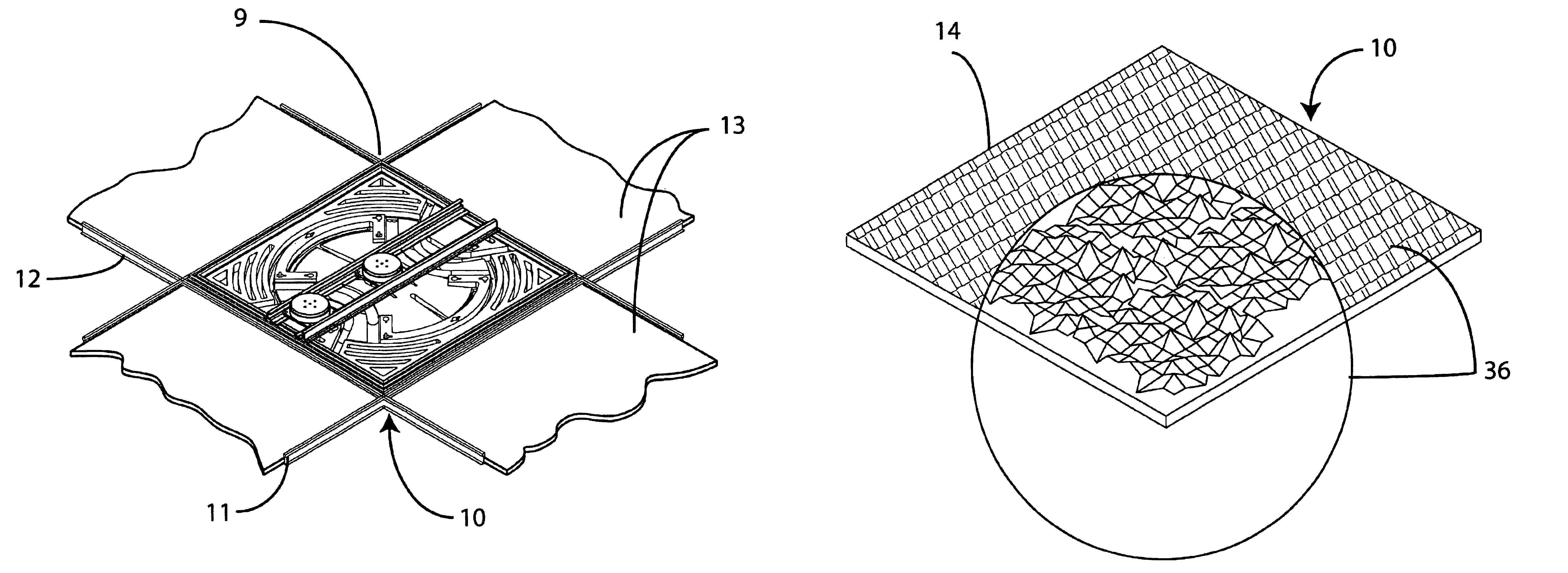
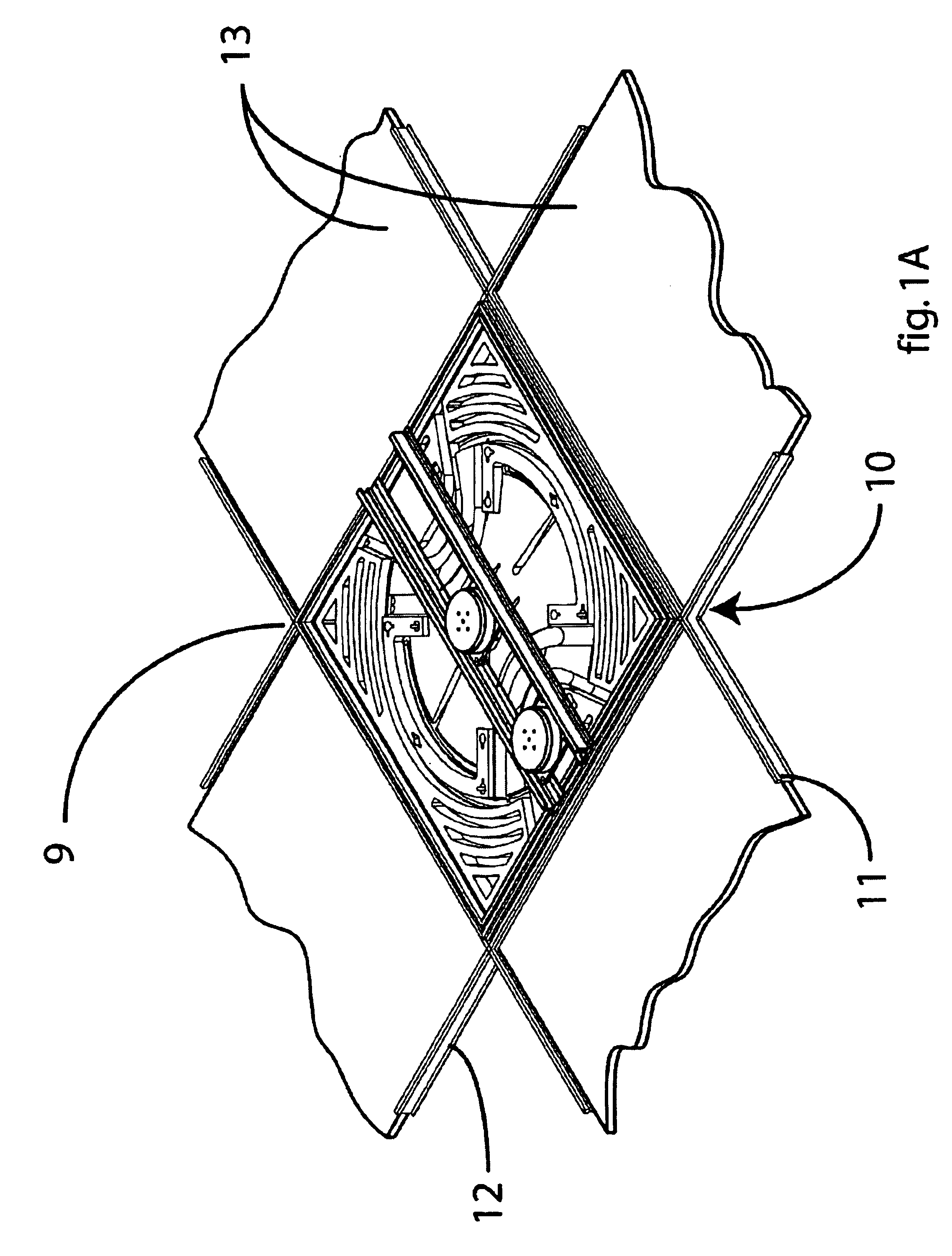
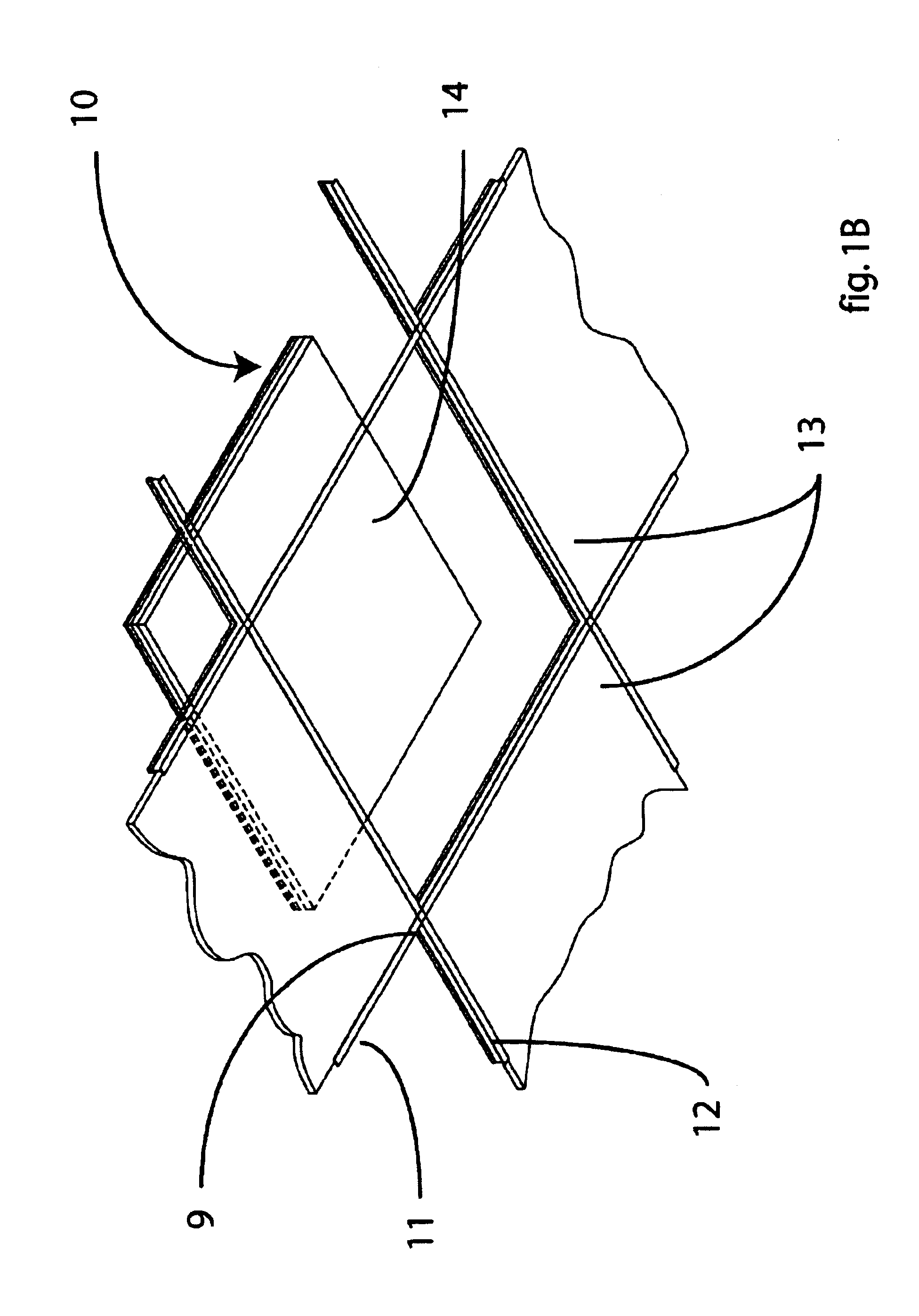
[0057]Referring now to the drawings, and more particularly to FIGS. 1A and 1B, there is shown a planar diaphragm loudspeaker, indicated generally by reference numeral 10, suitable for use in a suspended ceiling grid 9 that typically comprise a series of metallic runners 11 and tees 12 forming a 2′×2′ or 2′×4′ grid onto which multiple acoustic ceiling tiles 13 are placed. The loudspeaker 10 is shown in FIG. 1B with the exposed surface 14 facing down, and ready to be placed at an opening of the suspended ceiling grid.

[0058]FIG. 2A illustrates an exemplary arrangement of a dual-driver planar diaphragm loudspeaker 30 resting on runners 11 of a suspended ceiling grid 9, whereas an electromagnetic driver assembly 15 includes a voice coil assembly 17 arranged for reproduction of low frequencies and where an electromagnetic driver assembly 16 includes a voice coil assembly 18 arranged for reproduction of high frequencies, and where both voice coil assemblies 17 and 18 are coupled with epoxy...


PUM


Abstract

A planar diaphragm loudspeaker for use in a suspended ceiling grid and related methods of manufacturing are provided. The loudspeaker includes a rectangular, planar diaphragm of polymer material sized to fill an opening of the ceiling grid. The front surface of the diaphragm defines a three-dimensional, textured pattern formed by a secondary operation, such as, etching, perforating, and adhesion of granular or fiber material. The diaphragm may include an outer region about the periphery of the diaphragm having a density of at least 5 pcf and an inner region circumscribed by the outer region, thereby providing sufficient structural stiffness to the outside perimeter of the diaphragm and eliminating the need of an outer frame. The density of the inner region is at or below about 3 pcf throughout the inner region. Also, a shroud may secured to the diaphragm, in which the shroud and the diaphragm are securable in a first orientation for flush mounting or in a second orientation for tegular-drop mounting. The loudspeaker may also include a bracket rigidly attached to the diaphragm at two spaced locations in the outer region and extending across the inner region between the spaced locations.

Description

[0001]This application claims the benefit of U.S. Provisional Application No. 60 / 421,718, filed Oct. 28, 2002.BACKGROUND OF THE INVENTION[0002]The present invention relates generally to an acoustic transducer or loudspeaker and, more particularly, to planar loudspeakers for use in suspended ceilings.[0003]Advances in dynamic loudspeakers have been provided by the advent of planar diaphragm loudspeakers. Examples of such planar loudspeakers are shown and described in U.S. Pat. Nos. 4,003,449 and 4,997,058, both issued in the name of Jose J. Bertagni. Further examples are described in U.S. Pat. Nos. 5,425,107, 5,539,835 and 5,693,917 issued to Alejandro Bertagni et al.[0004]Planar loudspeakers can be manufactured in various shapes and sizes, and used in a multitude of applications. For example, planar loudspeakers have been used in suspended ceiling structures of the type found in commercial buildings. Such suspended ceilings typically comprise a series of metallic runners and tees fo...

Claims


Application Information

Patent Timeline
IPC IPC(8): H04R7/04H04R7/00H04R1/02
CPCH04R1/02H04R7/04H04R2201/021H04R2307/029H05K5/02
Inventor BERTAGNI, ALEJANDROBERTAGNI, EDUARDOFERRIN, ALFREDO
Owner AUDIO TECH ASSOC
Why Eureka
Try Eureka