

headset
a headset and headphone technology, applied in the field of headsets, can solve the problems of difficult to hear ambient sound, disadvantageous earphones in outdoor use, and disadvantageous earphones, and achieve the effect of ambient sound and high-quality sound reproduction
- Summary
- Abstract
- Description
- Claims
- Application Information
AI Technical Summary
Benefits of technology
Problems solved by technology
Method used
Image

Examples
first embodiment
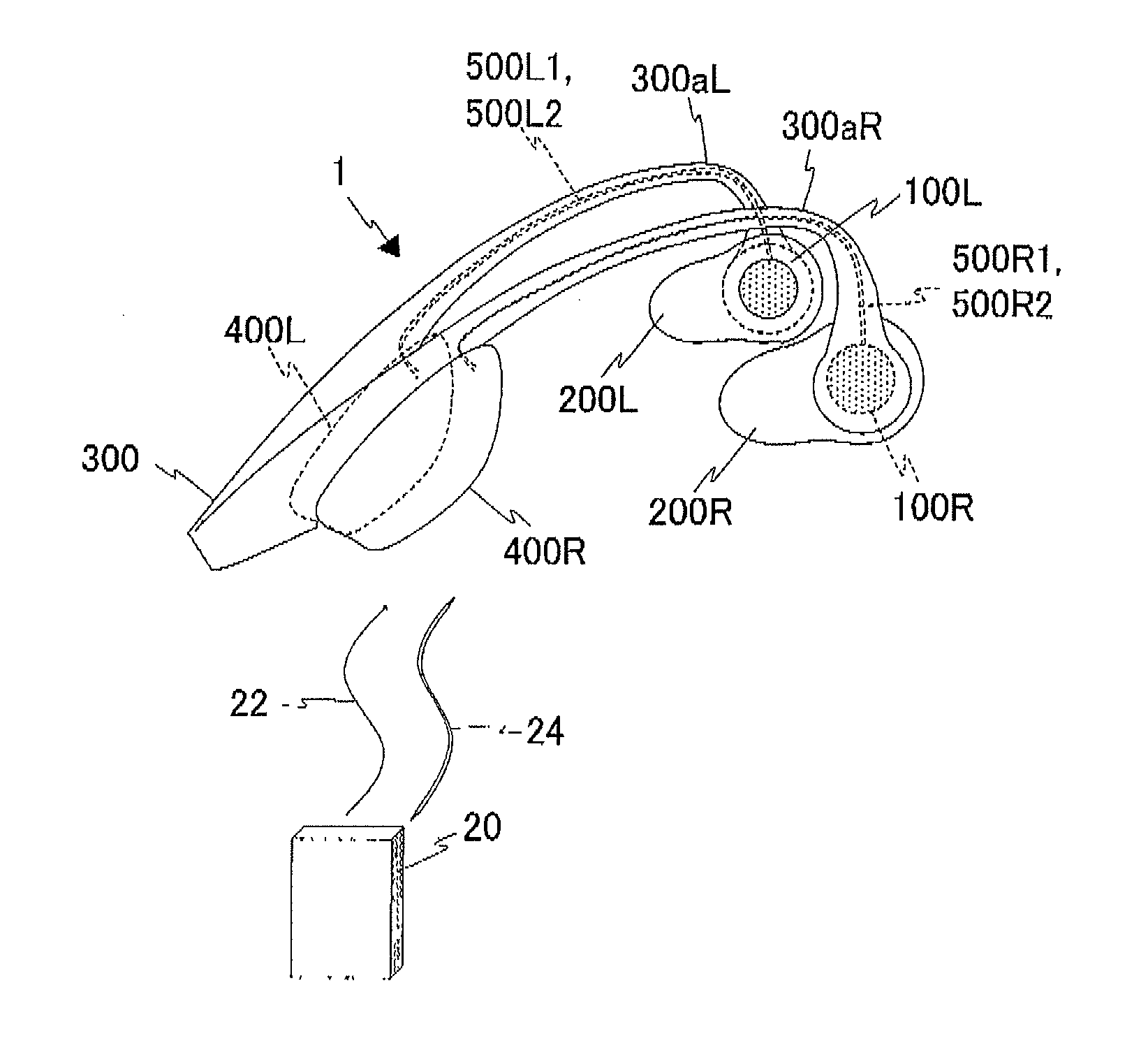
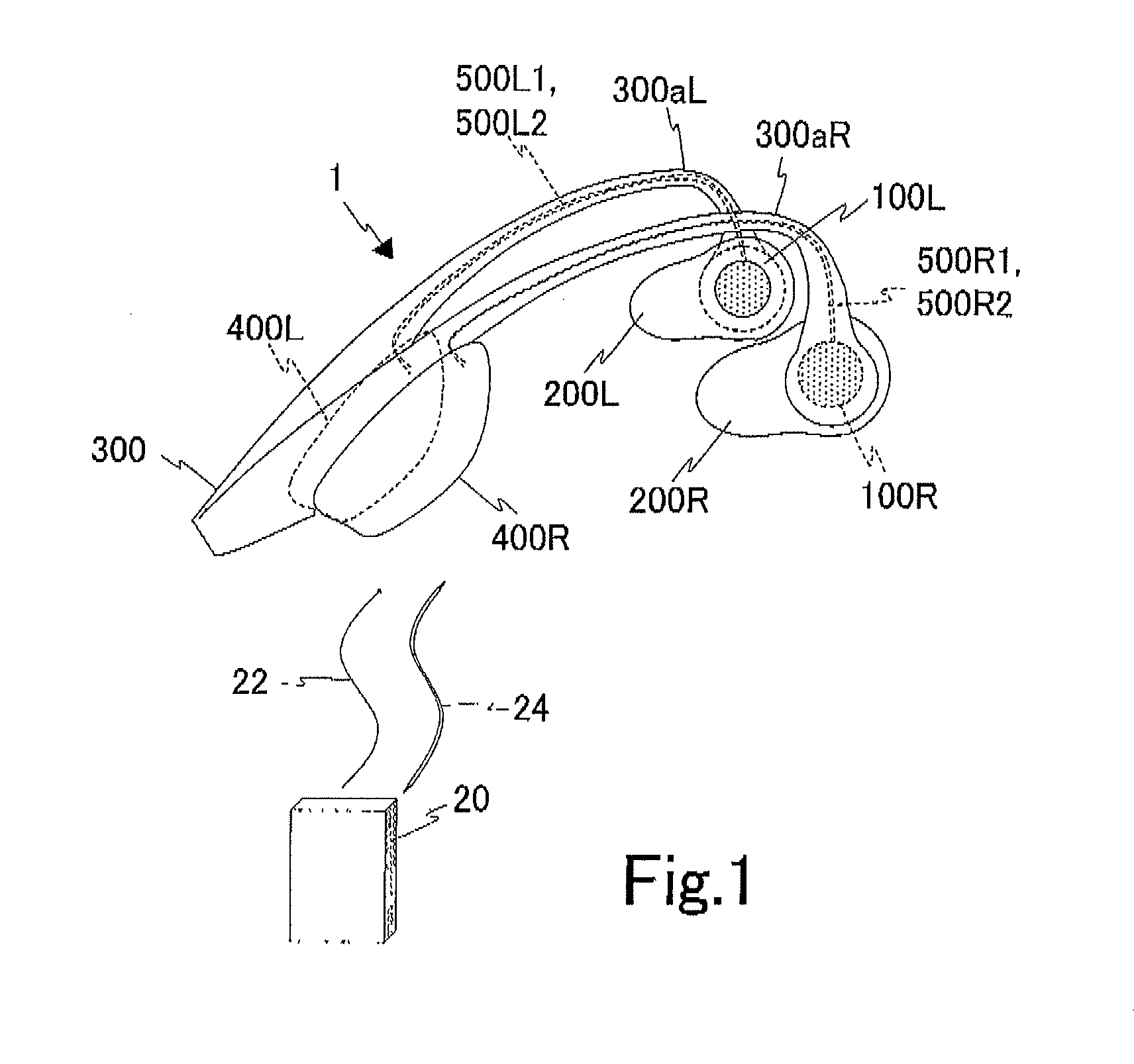
FIG. 1 depicts a headset 1 of the first embodiment of the present invention. The headset 1 includes vibrators 100R and 100L, diaphragms 200R and 200L, a linking unit (holding unit) 300, and control units 400R and 400L. The vibrator 100R and diaphragm 200R are used for the user's right ear, and the vibrator 100L and diaphragm 200L are used for the user's left ear. The diaphragms 200R and 200L are attached to opposite ends of the linking unit 300.
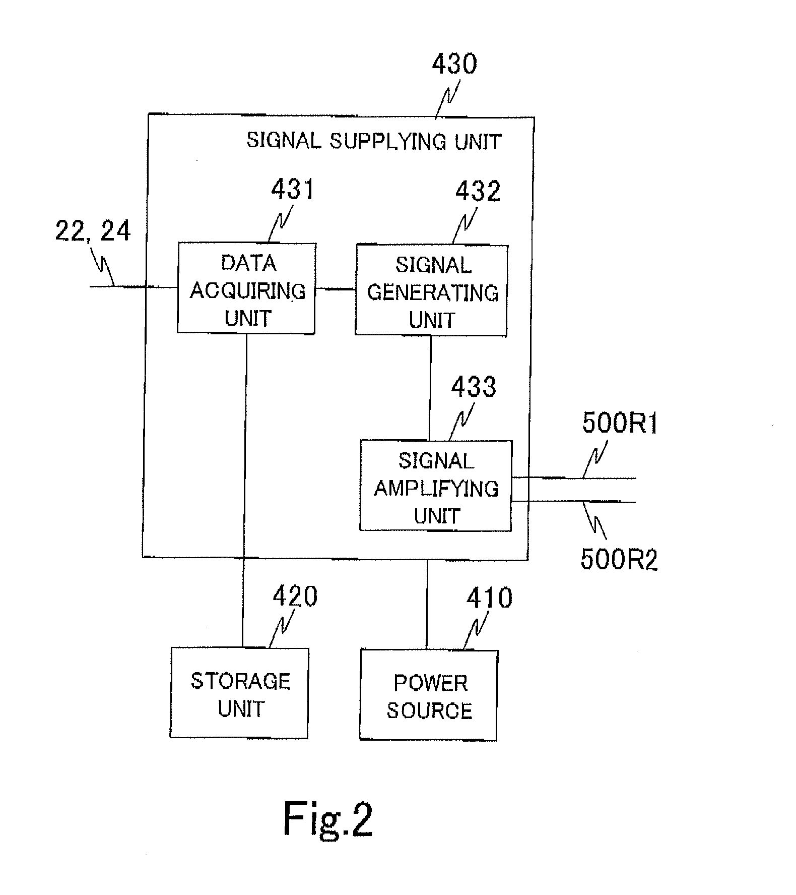
The vibrator 100R is configured to mechanically (or physically) vibrate in accordance with electric signals supplied from the outside. The electric signals are representative of, for example, music. The structure of the vibrator 100R will be described later (FIGS. 16 and 17). The right vibrator 100R is fixed to the inner surface of the right diaphragm 200R with an adhesive, for example. The left vibrator 100L has the same configuration as the vibrator 100R, and is fixed to the inner surface of the left diaphragm 200L.
The diaphragm 200R is gen...
second embodiment
The second embodiment of the present invention will be described with reference to FIG. 7a to FIG. 8b. The headset 2 according to the second embodiment has movable diaphragms 204R and 204L.
FIG. 7a depicts the headset 2 with the movable diaphragms 204R and 204L in the open state (open position). FIG. 7b depicts the headset 2 with the diaphragms 204R and 204L in the closed state (closed position). The following description will primarily deal with differences between the first and second embodiments.
The diaphragm 204R is attached to one end of the linking unit 300 such that it can rotate in the directions indicated by the arrows 81 and 82 about the rotation shaft 302R. Likewise, the diaphragm 204L is attached to the other end of the linking unit 300 such that it can rotate in the directions indicated by the arrows 81 and 82 about a rotation shaft 302L. The sidewall 200bR is provided on a peripheral edge of the base portion 200aR of the diaphragm 204R except a predetermined portion the...
third embodiment
The third embodiment of the present invention will now be described. FIG. 9 shows a headset 3 of the third embodiment. Portions different from the first and second embodiments will hereinafter mainly be described.
A ring-shaped (or annular) unit 310R is disposed at one end of the linking unit 300. A circular-shaped diaphragm 206R is fit into the ring of the annular unit 310R such that the diaphragm is able to rotate in the annular unit in the directions indicated by the arrows 83 and 84 about the center of the circular shape. The vibrator 100R is fixed to the inner surface of the diaphragm 206R, i.e., on the side facing the head when the headset is worn. Specifically, the vibrator 100R is fixed at a position offset from the center of the circular diaphragm 206R, and the position is moved by the rotation of the diaphragm 206R. A user can touch and rotate the diaphragm 206R with fingers. The diaphragm 206R may have grooves on its outer surface for finger friction (not depicted) to faci...
PUM
 Abstract
Description
Claims
Application Information