
Speaker

a technology of speaker and spherical body, applied in the field of speakers, can solve the problems of large distortion, abnormal noise depending on the speaker, energy loss, etc., and achieve the effects of reducing noise, excellent low frequency sound reproduction, and effective control of oscillation amplitud

Inactive Publication Date: 2012-12-20
PANASONIC CORP
View PDF2 Cites 2 Cited by
  • Summary
  • Abstract
  • Description
  • Claims
  • Application Information

AI Technical Summary

Benefits of technology

[0008]The present invention resides in a speaker capable of effectively controlling the amplitude of oscillation in large-amplitude oscillations and of excellent low frequency sound reproduction, thus being able to reproduce high quality sound. The speaker of the present invention includes a frame, a magnetic circuit secured to the frame, a voice coil, a damper, and a diaphragm. The diaphragm is secured to the frame and the voice coil. The voice coil is inserted in a magnetic gap of the magnetic circuit. The damper is secured to the voice coil and the frame and formed with a plurality of corrugations. One of the plurality of corrugations located on an inner circumferential side of the damper is provided with a plurality of apertures, and these apertures are covered by an elastic member.
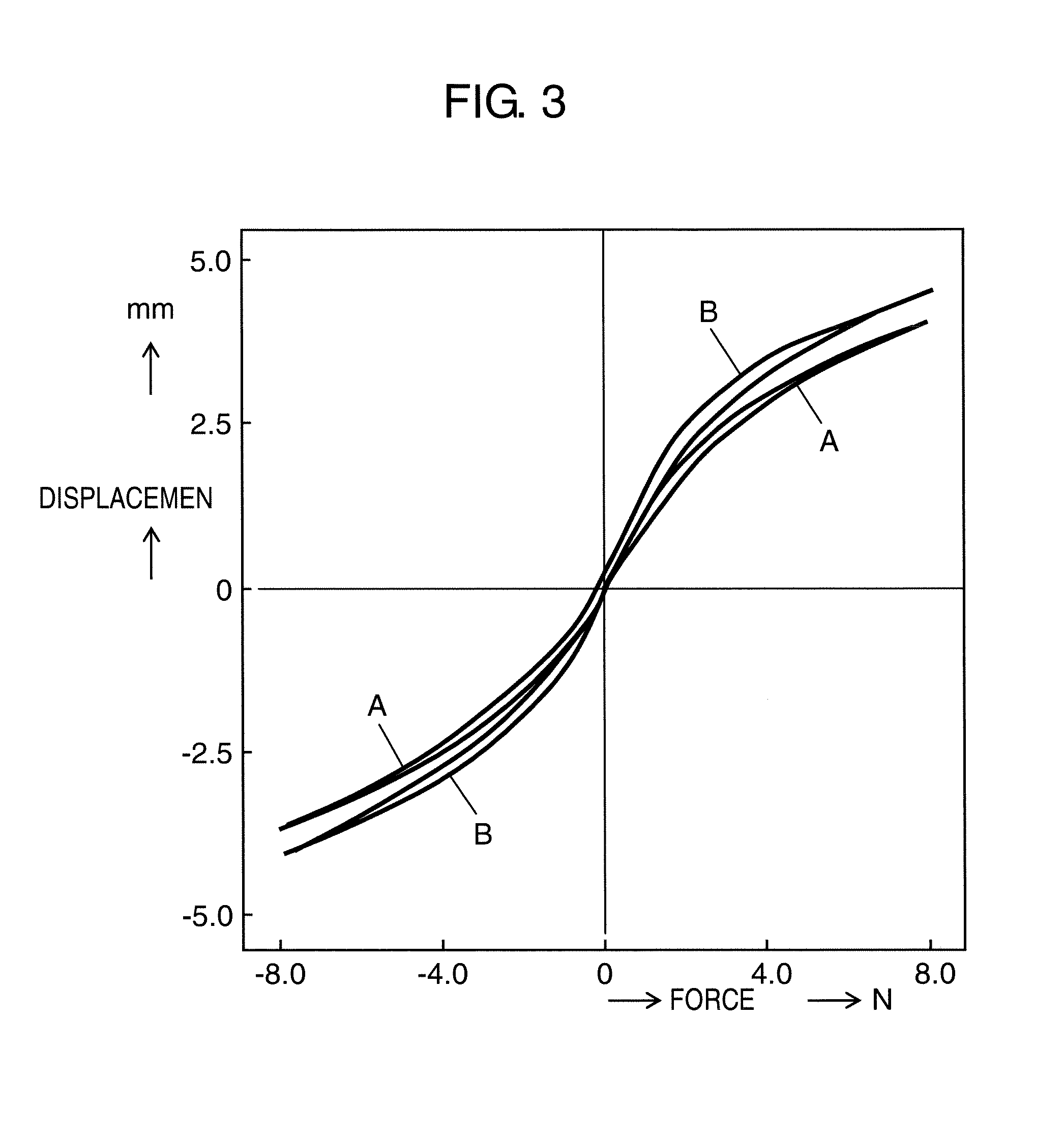
[0009]With the configuration described above, the speaker of the present invention is capable of high quality sound reproduction from input signals with high fidelity, as the corrugation in the inner circumferential part of the damper with apertures has higher flexibility and displaces first in small-amplitude oscillations. Parts of the damper other than the inner circumferential part without the apertures and having lower flexibility displace primarily in large-amplitude oscillations. Thereby, the speaker can readily oscillate at small amplitude where the magnetic flux is sufficiently applied to the voice coil and reproduce excellent low frequency sound, while the damper reduces the amplitude of oscillation of the voice coil at large amplitude to reduce distortion or abnormal noise.

Problems solved by technology

For this reason, large distortion can readily occur in large-amplitude oscillations, which may cause an abnormal noise depending on the speaker.
This leads to an energy loss and reduces the reproduction level of low frequency sound.
However, the effect of controlling the amplitude of oscillation is small with this configuration.

Method used


Image

  • Speaker
  • Speaker
  • Speaker

Examples


Embodiment Construction

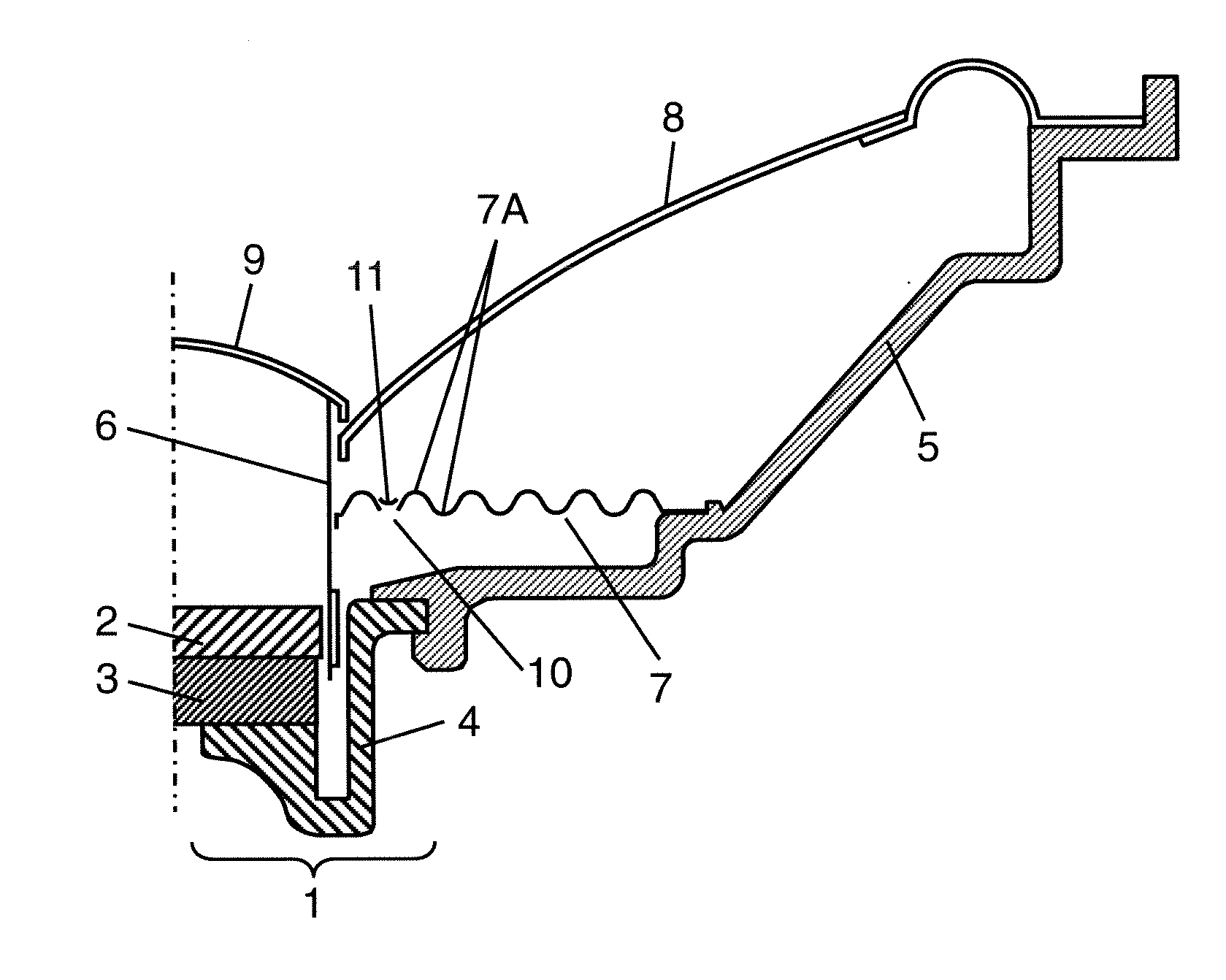
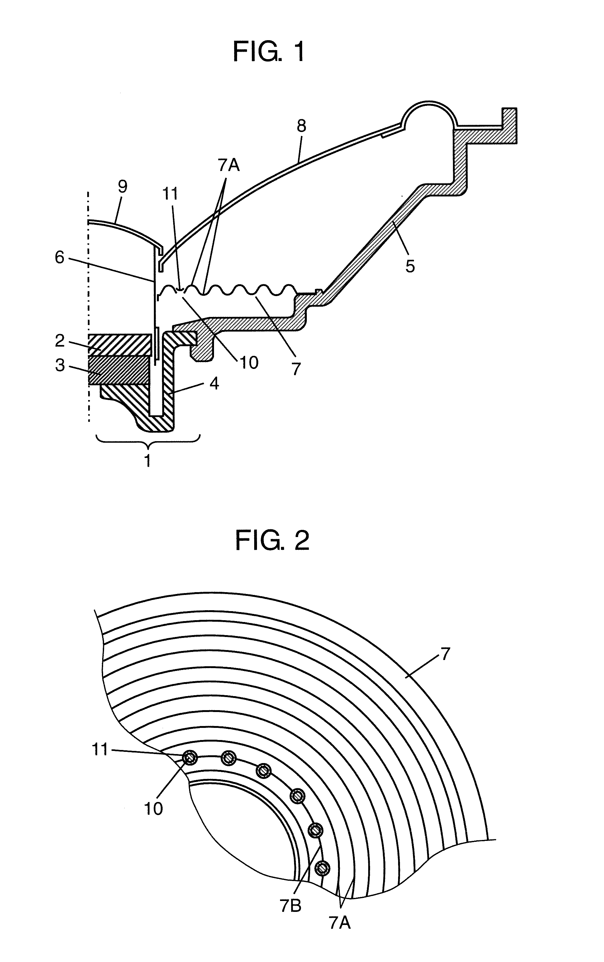
[0014]FIG. 1 is a half cross-sectional view of a speaker according to one embodiment of the present invention. FIG. 2 is an enlarged plan view of essential parts of the damper of this speaker. This speaker has frame 5, magnetic circuit 1, voice coil 6, damper 7, diaphragm 8, and dust cap 9. Magnetic circuit 1 includes magnet 3, plate 2 secured to an upper face of magnet 3, and yoke 4 secured to a lower face of magnet 3 and frame 5. A magnetic gap is formed between plate 2 and yoke 4. Magnetic circuit 1 is secured in an opening provided substantially in the center of frame 5.

[0015]Voice coil 6 is inserted in the magnetic gap of magnetic circuit 1. Damper 7 is secured to voice coil 6 and frame 5, and diaphragm 8 is secured to frame 5 and voice coil 6.

[0016]Damper 7 is formed with a plurality of corrugations 7A, 7B in a concentric manner. Corrugation 7B provided on an inner circumferential side of damper 7 is provided with a plurality of apertures 10, with elastic member 11 covering an...


PUM


Abstract

A speaker includes a frame, a magnetic circuit secured to the frame, a voice coil, a damper, and a diaphragm. The voice coil is inserted in a magnetic gap of the magnetic circuit. The damper is secured to the voice coil and the frame and formed with a plurality of corrugations. The diaphragm is secured to the frame and the voice coil. One of the plurality of corrugations located on an inner circumferential side of the damper is provided with a plurality of apertures, and these apertures are covered by an elastic member.

Description

TECHNICAL FIELD[0001]The present invention relates to a speaker used in various acoustic devices.BACKGROUND ART[0002]FIG. 4 is a half cross-sectional view of a conventional speaker. This speaker has magnetic circuit 21, frame 25, voice coil 26, damper 27, diaphragm 28, and dust cap 29. Magnetic circuit 21 includes plate 22, magnet 23, and yoke 24.[0003]When a large input is applied to this speaker and voice coil 26 oscillates with an amplitude of more than a certain level, voice coil 26 goes beyond an appropriate range of the magnetic flux of magnetic circuit 21. This changes the magnetic flux applied to voice coil 26 from magnetic circuit 21, generating distortion. For this reason, large distortion can readily occur in large-amplitude oscillations, which may cause an abnormal noise depending on the speaker.[0004]To improve this problem of abnormal noise, a speaker controlling the amplitude of oscillation has been devised, which actively suppresses displacement of the damper when th...

Claims


Application Information

Patent Timeline
Patent Type & Authority Applications(United States)
IPC IPC(8): H04R11/02
CPCH04R9/043H04R2400/00
Inventor YAMAGISHI, KIYOSHI
Owner PANASONIC CORP
Learn More