Composite pipe

a technology of composite pipes and pipes, applied in the direction of mechanical equipment, synthetic resin layered products, other domestic articles, etc., can solve the problems of composite pipes of unknown quality that require further testing and certification, and corrosion has always been a problem

Inactive Publication Date: 2006-11-23
WATSON WILLIAM R
View PDF61 Cites 20 Cited by
  • Summary
  • Abstract
  • Description
  • Claims
  • Application Information

AI Technical Summary

Benefits of technology

The invention relates to a method of joining pipes in a water-tight manner. The method involves using a polyethylene pipe or tube as a piling, and extending it beyond the ends of the core pipe. The open ends of the polyethylene pipe or tube are closed by plastic caps that are thermal fusion plastic welded or chemically welded in a water-tight manner. When a steel pipe is used in a string to form a pipe line, the steel pipe is extended beyond the polyethylene pipe or tube to expose short length of the core pipes. Adjacent pipes are then steel welded or otherwise joined, and "clamshell" portions of polyethylene material is chemically or thermal fusion welded between the polyethylene pipe or tube of adjacent pipes in a water-tight manner. The technical effect of this method is the creation of a water-tight joint between pipes that is durable and reliable.

Problems solved by technology

The technical problem addressed by this patent is how to create high-quality plastic-metal composite pipes with reliable structures for various industrial uses without requiring expensive and time-consuming tests and certifications.

Method used


Image

  • Composite pipe
  • Composite pipe
  • Composite pipe

Examples


Embodiment Construction

[0021] In the Figures, like numerals indicate like elements.

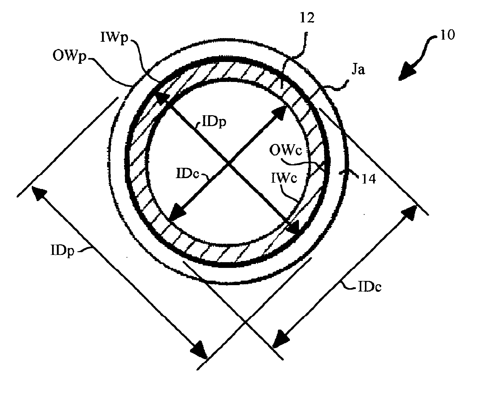
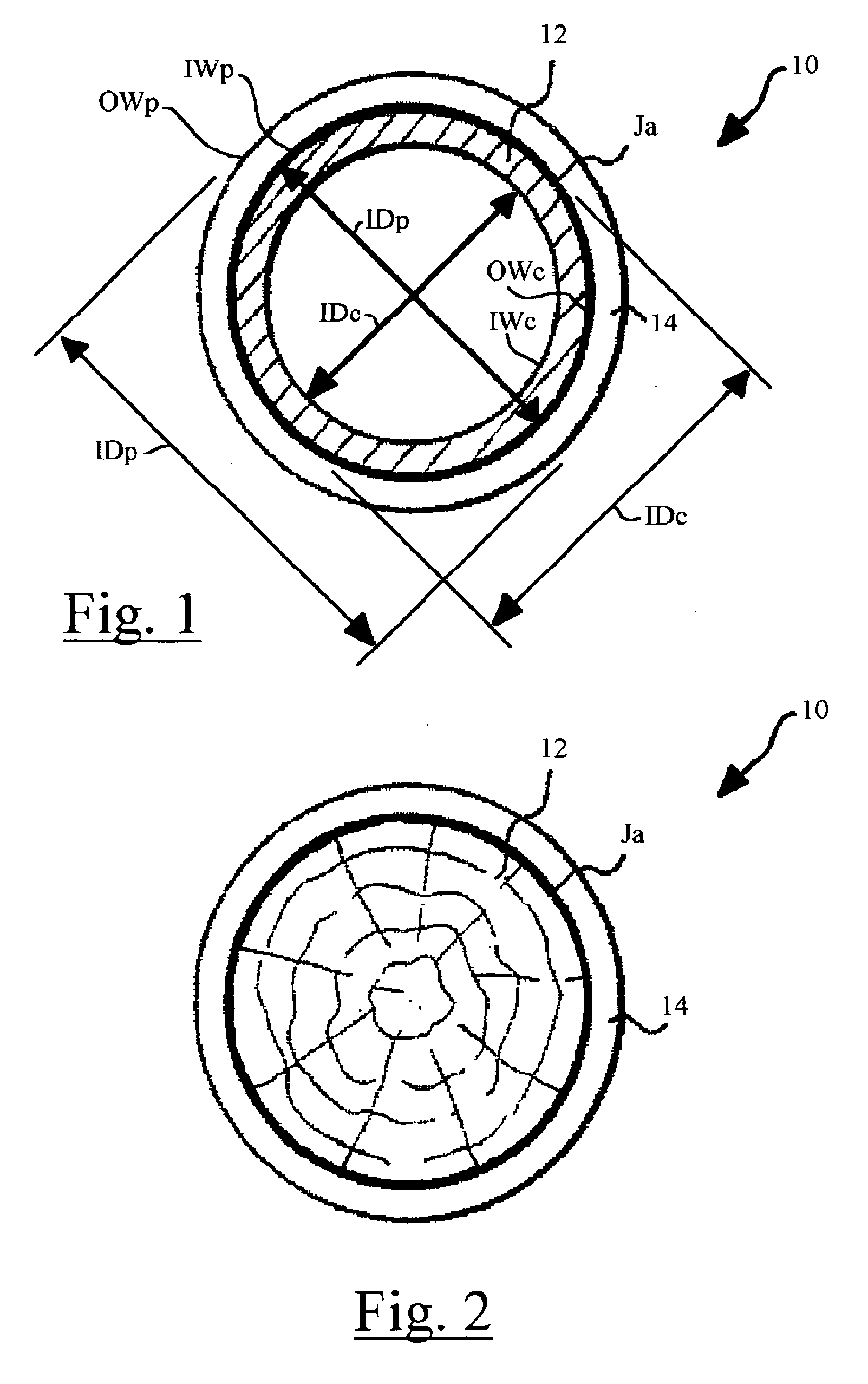
[0022]FIG. 1 is an end view that illustrates the present invention by example and without limitation embodied as a composite structural device formed of an elongated substantially cylindrical hollow pipe core material having an outer peripheral skin formed of a sleeve of seamless extruded or seam welded plastic pipe that is adhered to the core material by friction caused by radial compression.

[0023] As illustrated in FIG. 1, the composite structural device 10 of the invention is formed of an elongated substantially cylindrical metal pipe core 12 having an outer peripheral skin formed of a sleeve of seamless extruded or seam welded plastic pipe 14. The plastic pipe sleeve 14 is adhered to the metal pipe core 12 by intersurface friction caused by radial compression that results from the plastic pipe sleeve 14 having a nominal inside diameter IDp before installation that is the substantially same or smaller than an outside d...


PUM

PropertyMeasurementUnit
Fractionaaaaaaaaaa
Lengthaaaaaaaaaa
Timeaaaaaaaaaa

Abstract

A sleeved composite pipe or piling structure formed of an elongated polyethylene pipe or tube of high-density polyethylene (HDPE) or another polyethylene material installed over a substantially rigid and incompressible hollow metal pipe or solid wood core having an outer diameter that is the same or slightly larger than a normal inside diameter of the polyethylene pipe or tube when measured in a relaxed state at ambient temperature. The polyethylene pipe or tube is, for example, a HDPE 3408 material formed of virgin PE 3408 resin as specified in ASTM D3350 with UV protection, and the pipe is produced to ASTM A-3408. The metal pipe core can be ferrous or nonferrous pipe.

Description


Claims


Application Information

Patent Timeline
Owner WATSON WILLIAM R
Why Eureka
Try Eureka