Thermal transfer and power generation devices and methods of making the same

a technology of heat transfer and power generation device, which is applied in the direction of thermoelectric devices, transportation and packaging, electrochemical generators, etc., can solve the problems of limited lifetime, high cost and low efficiency of existing thermoelectric devices, and existing heat transfer devices such as those relying on refrigeration cycles

Inactive Publication Date: 2006-11-30
GENERAL ELECTRIC CO
View PDF28 Cites 138 Cited by
  • Summary
  • Abstract
  • Description
  • Claims
  • Application Information

AI Technical Summary

Problems solved by technology

However, existing heat transfer devices, such as those relying on refrigeration cycles, are environmentally unfriendly, have limited lifetime, and are bulky due to mechanical components such as compressors and the use of refrigerants.
However, due to the relatively high cost and low efficiency of the existing thermoelectric devices, they are restricted to small scale applications, such as automotive seat coolers, generators in satellites and space probes, and for local heat management in electronic devices.
However, such techniques are time consuming, are relatively expensive, are limited to small-scale applications, and require significant expertise.

Method used


Image

  • Thermal transfer and power generation devices and methods of making the same
  • Thermal transfer and power generation devices and methods of making the same
  • Thermal transfer and power generation devices and methods of making the same

Examples


Embodiment Construction

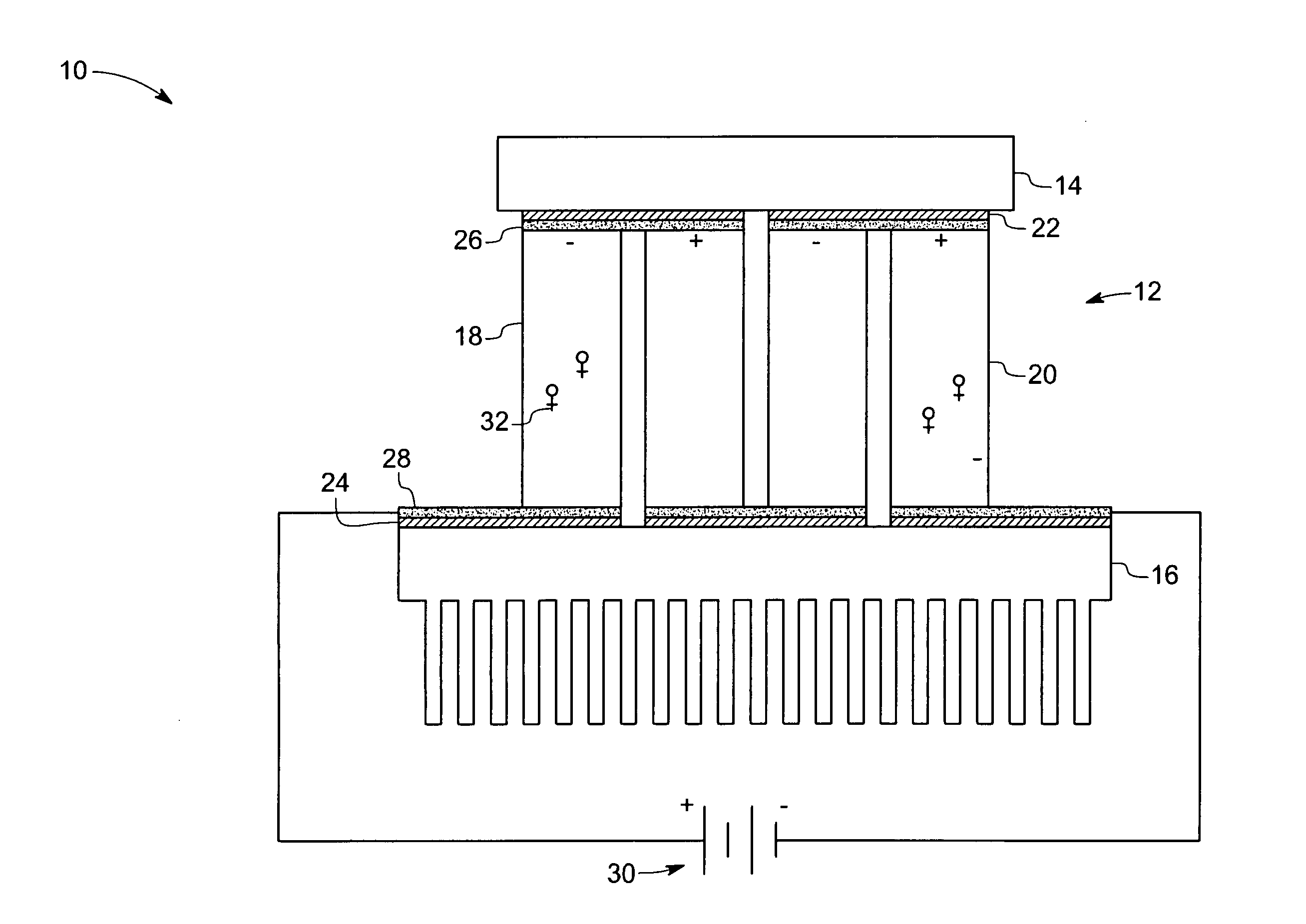
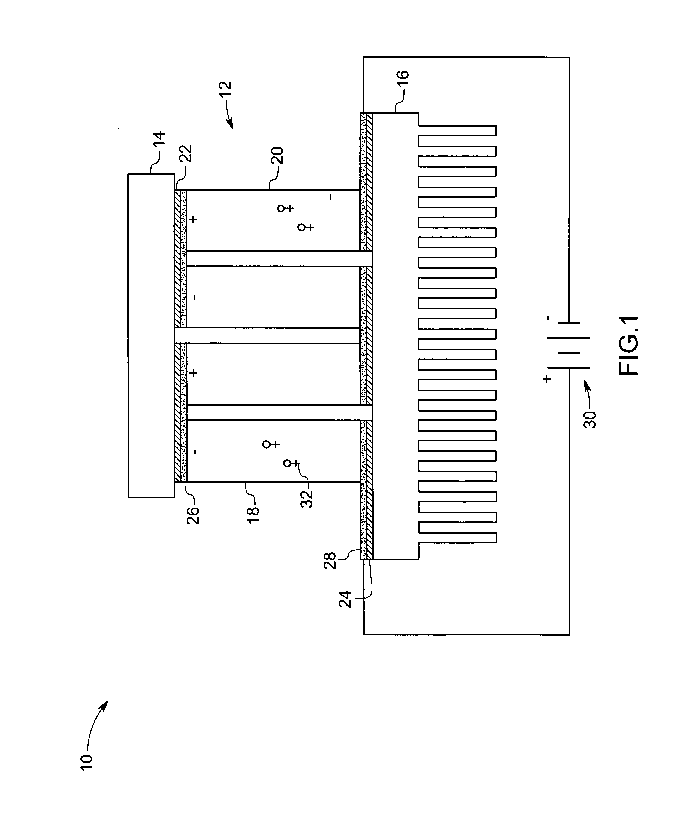
[0024] Referring now to the drawings, FIG. 1 illustrates a system 10 having a plurality of thermal transfer devices in accordance with certain embodiments of the present technique. As illustrated, the system 10 includes a thermal transfer module such as represented by reference numeral 12 that transfers heat from an area or object 14 to another area or object 16 that may function as a heat sink for dissipating the transferred heat. Thermal transfer module 12 may be used for generating power or to provide heating or cooling of the components. Further, the components for generating heat such as object 14 may generate low-grade heat or high-grade heat. As will be discussed below, the first and second objects 14 and 16 may be components of a vehicle, or a turbine, or an aircraft engine, or a solid oxide fuel cell, or a refrigeration system. It should be noted that, as used herein the term “vehicle” may refer to a land- based, an air-based or a sea-based means of transportation. In this ...


PUM


Abstract

A device includes a first thermally conductive substrate having a first patterned electrode disposed thereon and a second thermally conductive substrate having a second patterned electrode disposed thereon, wherein the first and second thermally conductive substrates are arranged such that the first and second patterned electrodes are adjacent to one another. The device includes a plurality of nanowires disposed between the first and second patterned electrodes, wherein the plurality of nanowires is formed of a thermoelectric material. The device also includes a joining material disposed between the plurality of nanowires and at least one of the first and second patterned electrodes.

Description

BACKGROUND [0001] The invention relates generally to heat transfer and power generation devices, and more particularly, to solid-state heat transfer devices. [0002] Heat transfer devices may be used for a variety of heating / cooling and power generation / heat recovery systems, such as refrigeration, air conditioning, electronics cooling, industrial temperature control, waste heat recovery, and power generation. These heat transfer devices are also scalable to meet the thermal management needs of a particular system and environment. However, existing heat transfer devices, such as those relying on refrigeration cycles, are environmentally unfriendly, have limited lifetime, and are bulky due to mechanical components such as compressors and the use of refrigerants. [0003] In contrast, solid-state heat transfer devices offer certain advantages, such as, high reliability, reduced size and weight, reduced noise, low maintenance, and a more environmentally friendly device. For example, therm...

Claims


Application Information

Patent Timeline
Patent Type & Authority Applications(United States)
IPC IPC(8): H01L35/30
CPCH01L35/30H01M8/12H01M16/00Y10T428/24273Y02E60/521Y02E60/525H01M2008/1293Y02E60/50H10N10/13
Inventor ZHANG, AN-PINGSEKER, FAZILACORDERMAN, REED ROEDERWEN, SHIXUESHARIFI, FREDSANDER, MELISSA SUZANNEYOUNG, CRAIG DOUGLAS
Owner GENERAL ELECTRIC CO
Why Eureka
Try Eureka