Electronic device featuring thermoelectric power generation

a technology of electronic devices and generators, applied in the manufacture/treatment of thermoelectric devices, thermoelectric devices, thermoelectric device details, etc., can solve the problems of insufficient sun or other light sources, low output, and inability to always be available, so as to reduce the probability of electrical shorting during operation.

Inactive Publication Date: 2001-09-11
CALIFORNIA INST OF TECH
View PDF4 Cites 47 Cited by
  • Summary
  • Abstract
  • Description
  • Claims
  • Application Information

AI Technical Summary

Benefits of technology

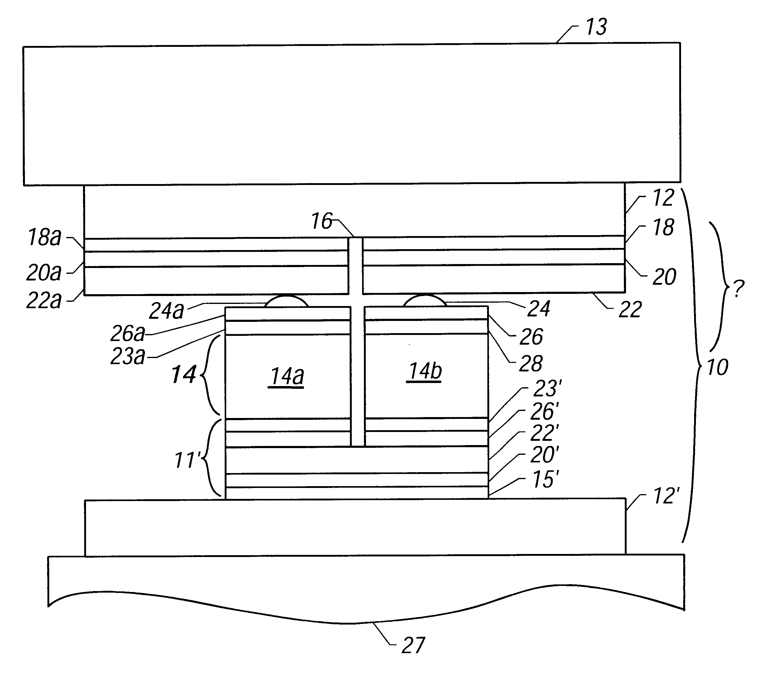
These devices may be constructed using microfabrication techniques. Microfabrication techniques are suitable because many hundreds or thousands of legs can be deposited and offer the potential to achieve an appropriate voltage / current combination for a given temperature differential across a device. Such techniques are also necessary to achieve the small size required for use in consumer electronics.
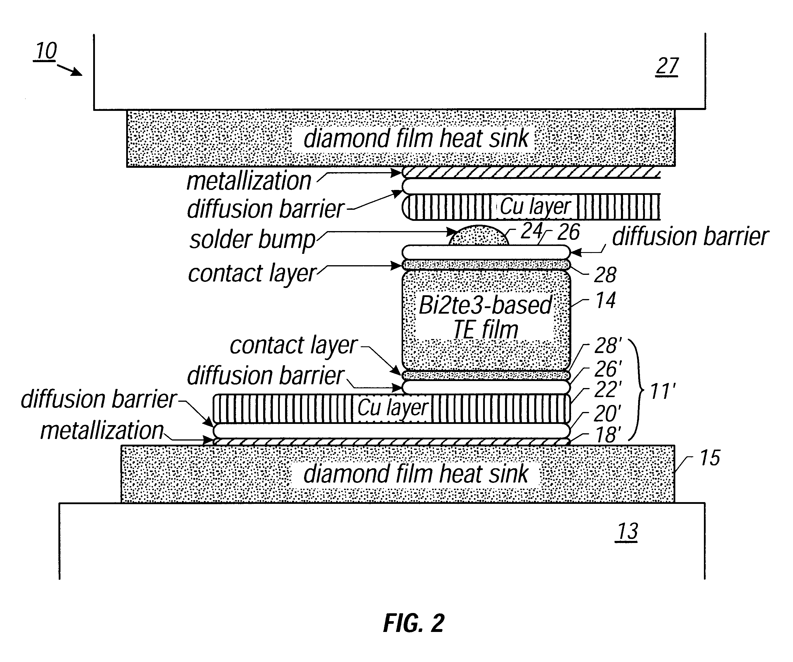
One way of depositing the TEG legs is by electrodeposition. In this way, once contact layer 28' is deposited as described above, the structure is placed in an electrodeposition bath and forms the cathode (or working electrode). Photoresist is previously applied on the entire area to be patterned. Patterns are etched onto the photoresist layer using photolithography where legs are not desired. A shallow Pt layer may be deposited on the structure prior to the structure entering the bath to protect the already-deposited layers.

Problems solved by technology

A disadvantage of batteries is, of course, that their energy dissipates over time, requiring battery replacement or recharging.
A disadvantage of solar power is that the sun or other light sources are not always available, and the power output is generally not large.

Method used


Image

  • Electronic device featuring thermoelectric power generation
  • Electronic device featuring thermoelectric power generation
  • Electronic device featuring thermoelectric power generation

Examples


Embodiment Construction

wristwatch application is described below as an example. It should be noted that any electronic device with similar power requirements may be powered similarly, as long as a thermal gradient is present.

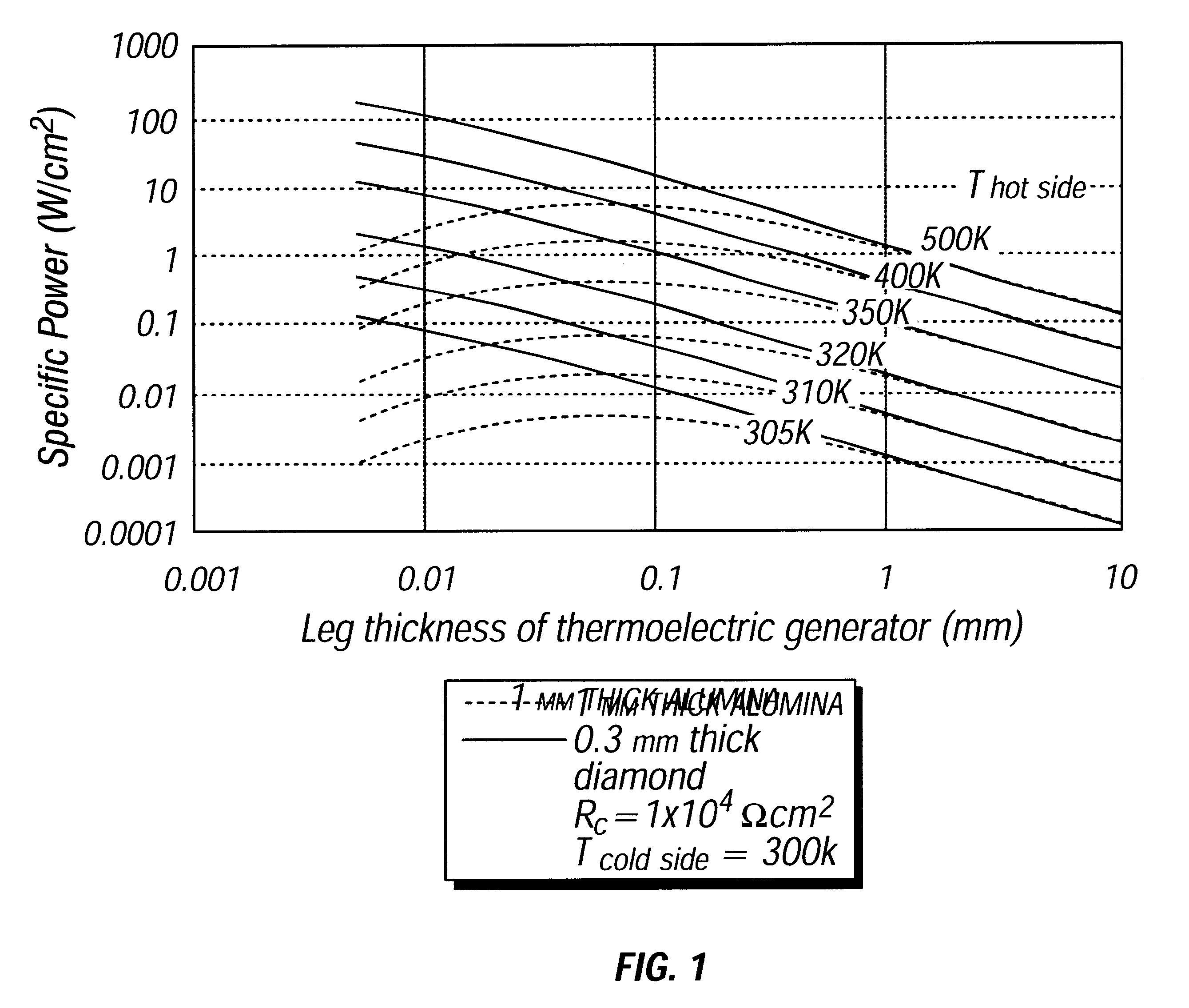
.DELTA.T may be as low as 1.degree. C. for a wristwatch application. This low .DELTA.T is assumed as an operating point due to uncertainty in the ambient environment and the efficiency of heat rejection. A desirable size for the TEG module may be in the range of about 1.5 mm.times.1.5 mm in such an application.

A basic heat collection area of 100 mm.sup.2 is considered (e.g., 10 mm.times.10 mm) for purposes of this discussion. Heat rejection occurs from the outer edge of the watch front, or face (the center is typically glass). Thus, it may be desirable for the TEG to be positioned around the circumference of the watch interior, drawing heat from the solid back, and rejecting heat to the periphery of the front side.

A thermal analysis of one potential watch configuration has been perfor...


PUM

PropertyMeasurementUnit
thicknessesaaaaaaaaaa
thicknessaaaaaaaaaa
thicknessaaaaaaaaaa

Abstract

A device for generating power to run an electronic component. The device includes a heat-conducting substrate (composed, e.g., of diamond or another high thermal conductivity material) disposed in thermal contact with a high temperature region. During operation, heat flows from the high temperature region into the heat-conducting substrate, from which the heat flows into the electrical power generator. A thermoelectric material (e.g., a Bi2Te3-based film or other thermoelectric material) is placed in thermal contact with the heat-conducting substrate. A low temperature region is located on the side of the thermoelectric material opposite that of the high temperature region. The thermal gradient generates electrical power and drives an electrical component.

Description

ORIGIN OF THE INVENTIONThe invention described herein was made in the performance of work under a NASA contract, and is subject to the provisions of Public Law 96-517 (35 Title U.S.C. 202) in which the contractor has elected to retain title.This invention relates to devices employing thermoelectric power generators, and more particularly to small electronic devices, such as consumer electronics, having small thermoelectric power generators as their power sources.Small electronic devices, such as those employing integrated circuits, continue to play a major role in all aspects of society. Batteries have traditionally been used to power such devices. Non-traditional energy sources include, e.g., solar power.A disadvantage of batteries is, of course, that their energy dissipates over time, requiring battery replacement or recharging. A disadvantage of solar power is that the sun or other light sources are not always available, and the power output is generally not large.One way to powe...

Claims


Application Information

Patent Timeline
Patent Type & Authority Patents(United States)
IPC IPC(8): H01L35/32H01L35/12H01L35/16H01L35/30
CPCH01L35/16H01L35/32H01L35/30H10N10/852H10N10/17H10N10/13
Inventor FLEURIAL, JEAN-PIERREOLSON, N. THOMASBORSHCHEVSKY, ALEXANDERCAILLAT, THIERRYKOLAWA, ELIZABETHRYAN, M. AMYPHILIPS, WAYNE M.
Owner CALIFORNIA INST OF TECH
Why Eureka
Try Eureka