
Carrying case with integrated electronics system

a technology of electronic system and carrying case, which is applied in the field of carrying cases, can solve the problems of varying the weight of one's baggage, not having ready access to scales or other weighing devices suitable for travelers,

Inactive Publication Date: 2006-11-30
KAPLAN MYRON DAVID
View PDF12 Cites 61 Cited by
  • Summary
  • Abstract
  • Description
  • Claims
  • Application Information

AI Technical Summary

Benefits of technology

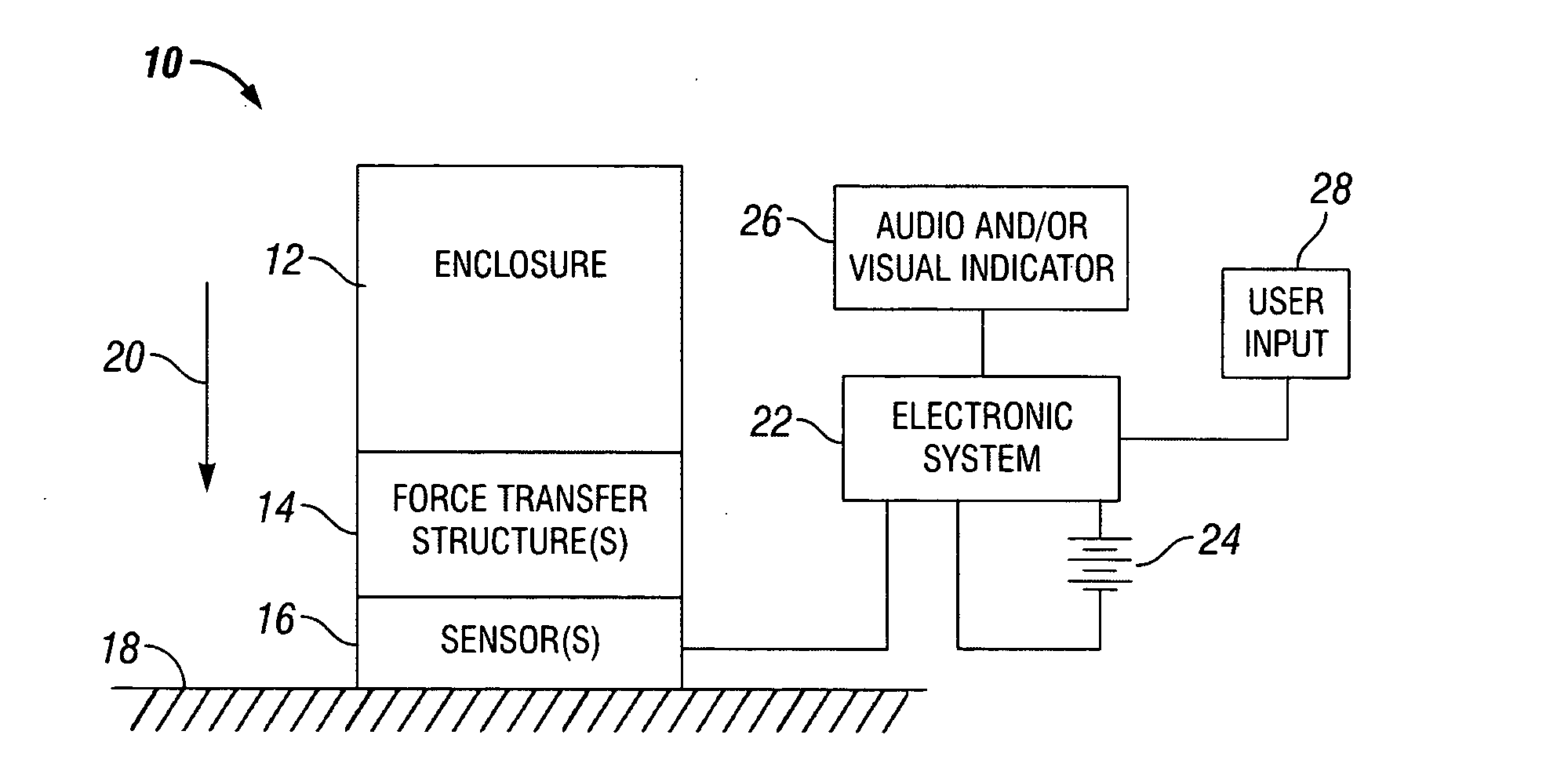
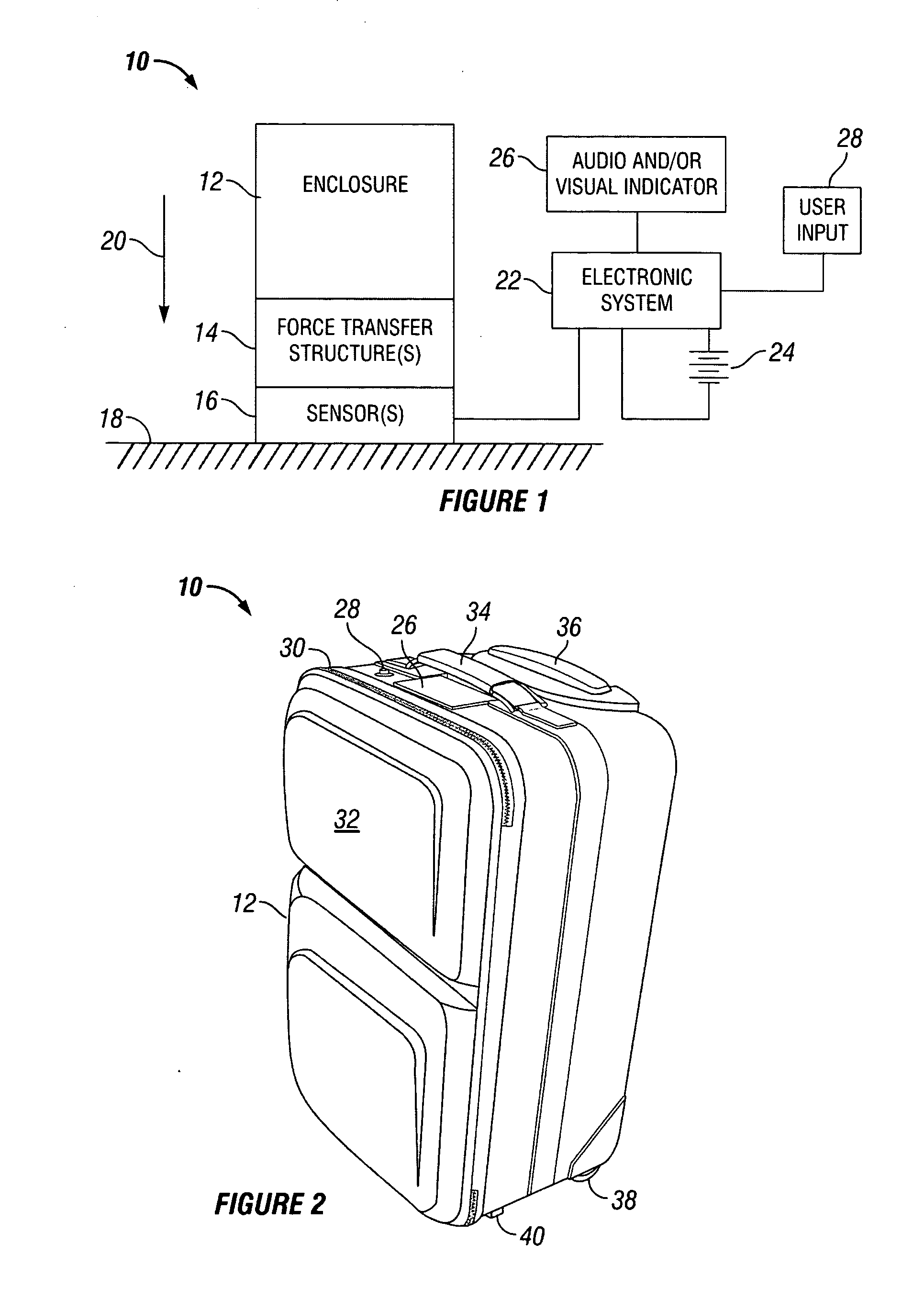
[0009] In an alternative embodiment of the invention, a suitcase with a handle is provided with one or more load / force sensors that are integrated into the suitcase in such a manner that when the suitcase is held above the ground by the handle, the weight of the suitcase and its contents is exerted on the sensor(s), thereby enabling the suitcase to be weighed.

Problems solved by technology

Second, airlines in the United States are required to conform to regulations imposed by the Occupational Health and Safety Administration respecting the maximum weight of items that baggage handlers and other employees are required to lift during the course of performing their duties.
When packing their bags, travelers typically do not have ready access to scales or other weighing devices suitable for determining whether a packed suitcase complies with an airline's weight restrictions, if the traveler even knows what those weight restrictions may be for each airline on which he or she may travel.
Moreover, the weight of one's baggage may vary throughout the duration of a given trip, such that a bag may be compliant on one leg of travel but non-compliant on another.

Method used


Image

  • Carrying case with integrated electronics system
  • Carrying case with integrated electronics system
  • Carrying case with integrated electronics system

Examples


case 10

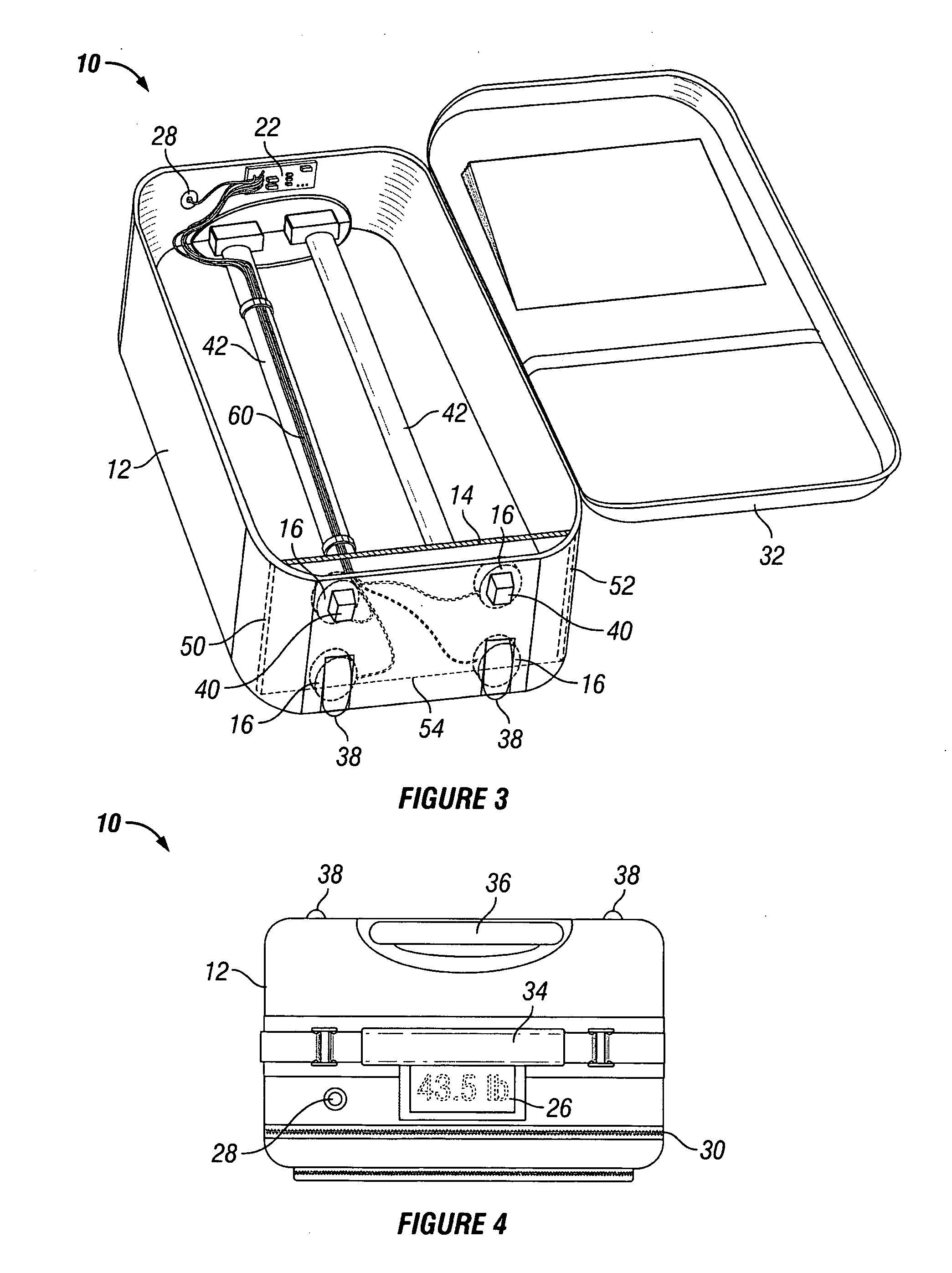
[0035] Carrying case 10 is further equipped with a fixed handle 34 secured on a top portion of enclosure 12. In accordance with conventional design, carrying case 10 is further equipped with a retractable handle 36 which extends into the interior of enclosure 12 and can be withdrawn upwardly to provide a convenient means for pulling the carrying case 10 along on its wheels 38.

[0036] Turning to FIG. 3, there is shown a perspective view of carrying case with zipper 30 unzipped and lid portion 32 in an open position. As can be observed in FIG. 3, and in accordance with the conventional design of suitcases such as in the presently disclosed embodiment, disposed on a bottom surface of enclosure 12 are a plurality of support structures. In particular, in the disclosed embodiment, there are two support posts 40 in addition to the two wheels 38. Together, posts 40 and wheels 38 cooperate to maintain enclosure 12 balanced in an upright position when placed on a reasonably level surface with ...


PUM


Abstract

A carrying case having an integrated electronic system is disclosed. In one embodiment, the carrying case resembles a conventional wheeled suitcase such as is commonly used by airline travelers. One or more load / force sensors are disposed on or near a bottom surface of the suitcase enclosure. Some means of force transfer is provided for ensuring that when the suitcase is resting on a substantially flat surface, the force from the weight of the suitcase itself and all of its contents are exerted on the sensor(s). An electronic system is disposed within the enclosure and is in electrical communication with the sensor(s). A user actuable input such as a pushbutton is mounted on the exterior of the enclosure. The electronic system is responsive to actuation of the input to perform a weighing operation whereby the output(s) from the sensor(s) are interpreted and supplied to an indicator for providing an indication of the weight of the carrying case and its contents. The indicator may be a visual indicator such as a digital display, and / or an audible indicator, such as a voice synthesizer circuit for reading an audible indication of the weight.

Description

FIELD OF THE INVENTION [0001] This invention relates generally to the field of carrying cases and the like, and more particularly relates to a carrying case having an integral electronic system for performing various functions. BACKGROUND OF THE INVENTION [0002] Those of ordinary familiarity with the logistics of traveling, especially traveling by aircraft, will appreciate that there are often constraints imposed on the baggage one uses to carry one's clothing, personal effects, and the like. [0003] In addition to quantity and size restrictions, commercial airlines throughout the world typically impose restrictions on the weight of one's baggage. These restrictions vary from time to time, from country to country, and from airline to airline. Most United States carriers have recently tightened their baggage restrictions, particularly their weight restrictions, and many have increased the fines or surcharges imposed on passengers whose baggage exceeds applicable standards. [0004] Airl...

Claims


Application Information

Patent Timeline
IPC IPC(8): G01G23/00G01G19/00
CPCG01G19/58G01G23/3742G01G23/3735
Inventor KAPLAN, MYRON DAVID
Owner KAPLAN MYRON DAVID
Learn More