Illumination method and system for obtaining color images by transcleral ophthalmic illumination

a transcleral ophthalmic and color image technology, applied in the field of illumination methods and systems for obtaining color images by transcleral ophthalmic illumination, can solve the problems of enlarge the observable field to the whole fundus, impede the ability of light that reaches the interior of the eye, and not dilate pupils, so as to achieve the effect of compromising eye safety

Inactive Publication Date: 2006-11-30
MEDIBELL MEDICAL VISION TECH
View PDF4 Cites 80 Cited by
  • Summary
  • Abstract
  • Description
  • Claims
  • Application Information

AI Technical Summary

Benefits of technology

The invention provides a way to get high-quality color images of the inside of the eye using a special lighting technique. This is important because it allows for the first time to see the retina in detail without damaging the eye. The method involves using a special light that can pass through the sclera and be strong enough to capture clear and high-resolution images. This can help with the diagnosis and treatment of various eye conditions.

Problems solved by technology

The technical problem addressed in this patent is the limitations of current fundus-viewing and imaging systems due to the need for pupil dilation and the resulting reflections and difficulties in observing the periphery of the eye. The invention provides an illumination method that can provide improved illumination for diagnostic and documentation purposes without the need for pupil dilation and can enlarge the observable field to the whole fundus. However, it is important to consider the optical properties of the tissue when using transcleral illumination, as this method transmits a maximum of 50% of red light and 10% of blue light, which compromises the ability to obtain color images based on red, green, and blue color component contributions.

Method used


Image

  • Illumination method and system for obtaining color images by transcleral ophthalmic illumination
  • Illumination method and system for obtaining color images by transcleral ophthalmic illumination
  • Illumination method and system for obtaining color images by transcleral ophthalmic illumination

Examples


second embodiment

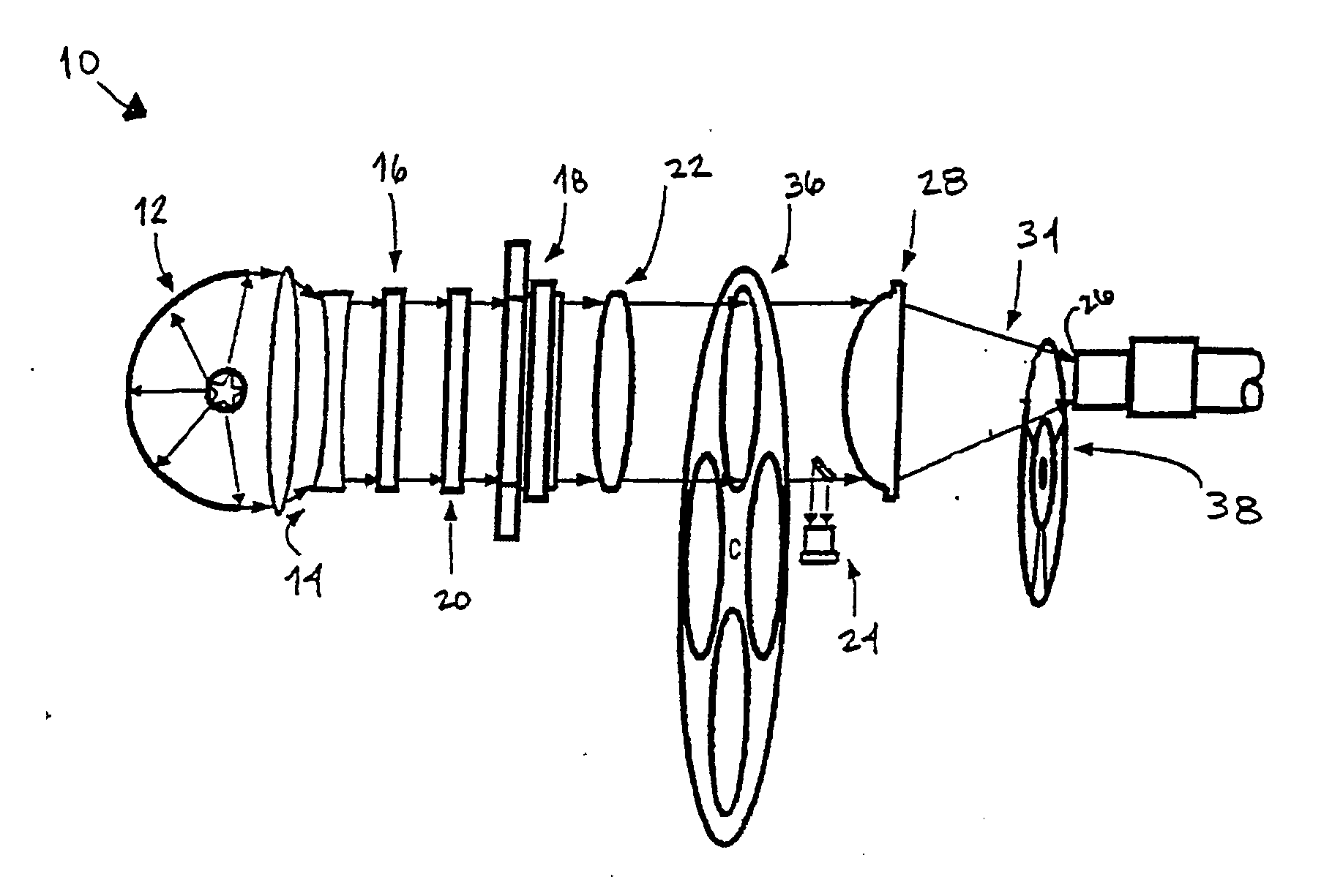
[0057]FIG. 3 shows illumination system 10, having a light path similar to that of FIG. 1, in which a halogen or metal-halide lamp 12 produces a well-defined collimated light beam, with the aid of matching beam-expander optics 14. Hot mirror 16 is placed in the optical path close to the light source to remove ultraviolet (UV) and infrared (IR) components of the light spectral content. In this embodiment, the main beam is split into three “colored” channels (R, Y, G) using R-Y-G dichroic “X-cube” splitter 40 with two 45° tilted mirrors 42 that deflect the side emerging channel beams to produce three parallel beams. To overcome a possible loss of some polarized light beam components due to polarization sensitivity of X-cube splitter 40, a polarization converter prism 44 is inserted in the light path preceding X-cube splitter 40, so as to transform the impinging randomly polarized light beam into a linearly polarized one.

[0058] Three electro-optical fast shutters 46 (by way of example, ...

third embodiment

[0060] Referring now to FIG. 4, illumination system 10 is shown in which the splitting of the main channel into R, Y and G sequential synchronized light bursts is accomplished using a series of three 45° tilted beam splitters: 30R / 70T (30% reflecting / 70% transmitting) beam splitter 52, 50R / 50T beam splitter 54 and 45° tilted mirror 56, and adding an R, Y or G optical filter to each of the channels. Alternatively, a series of three 45° tilted dichroic spectral beam splitters for R, Y and G may be used (e.g. J43-454, J43-455 and J43-458 correctors marketed by Edmund Scientific, Barrington, N.J., USA).

[0061] The use of three 45° tilted beam splitters is the least efficient method of color splitting, as compared to the embodiments shown in FIGS. 1 and 3, due to the partitioning of the total beam power into three separated channels with about one third of the total power content in each channel. Therefore, the optical filters in each channel separate out only part of the spectral content...


PUM


Abstract

An illumination system for fundus imaging apparatus employing transcleral illumination of the interior of the eye. Color images of the interior of the eye are obtained by illuminating the sclera successively with red, yellow and green light. Those images are then treated as red, green and blue images by a post processing unit, which combines them to give a color image. This is useful for observing or imaging the interior of the eye, the retina, or the choroid. The observation or the imaging of the interior of the eye, the retina, or the choroid by applying the disclosed illumination method can be performed in conjunction with any system that includes optics for that purpose.

Description


Claims


Application Information

Patent Timeline
Owner MEDIBELL MEDICAL VISION TECH
Why Eureka
Try Eureka