Supercharge Your Innovation With Domain-Expert AI Agents!

Automatic addressing method

a technology of automatic addressing and addressing devices, applied in the direction of digital transmission, data switching networks, electrical devices, etc., can solve the problems of wrong signals received by the receiving end, and achieve the effect of better signals

Inactive Publication Date: 2006-11-30
FTECH CORP
View PDF3 Cites 0 Cited by
  • Summary
  • Abstract
  • Description
  • Claims
  • Application Information

AI Technical Summary

Benefits of technology

"The present invention is a signal transmitting system that produces better signals. It includes an emitter, repeaters, and receivers. The repeaters communicate with each other to set delayed transmitting times and receive signals from the emitter. The receivers can receive the signals from the repeaters, but the next signal will be received after a time interval. The receiver of the invention receives the signals from the emitter and applies an automatic addressing method to avoid cross-talking with other repeaters. The repeater includes a receiving unit, transmitting unit, memory unit, and controlling unit. The controlling unit sends information about the repeaters in the same area and receives the information from other repeaters. It selects a unique number and sends out the information to other repeaters. The system includes a memory unit to store the numbers of the repeaters and transmit the signals to the receivers according to the delayed time. The automatic addressing method involves inquiring about the numbers of existing repeaters, selecting a unique number, and storing it in the memory unit. The system can improve signal quality and reduce interference."

Problems solved by technology

In addition, since the working frequency of the first repeater is similar to that of the second repeater in the same area, and amplified the signals that sent out from the sending end at once, and then transmitted, however, the signals that sent out simultaneously are usually cross-talked each other, result in the wrong signals received by the receiving end.

Method used


Image

  • Automatic addressing method
  • Automatic addressing method
  • Automatic addressing method

Examples


Embodiment Construction

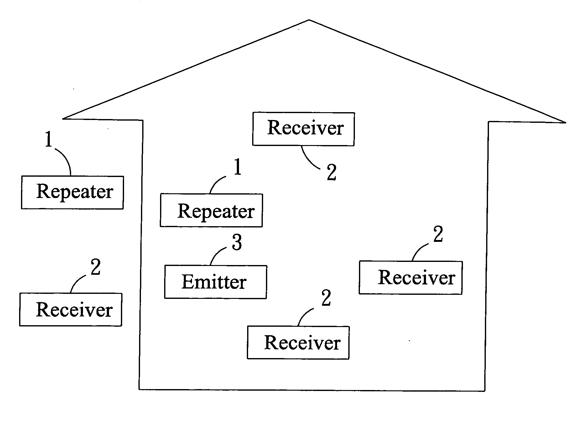
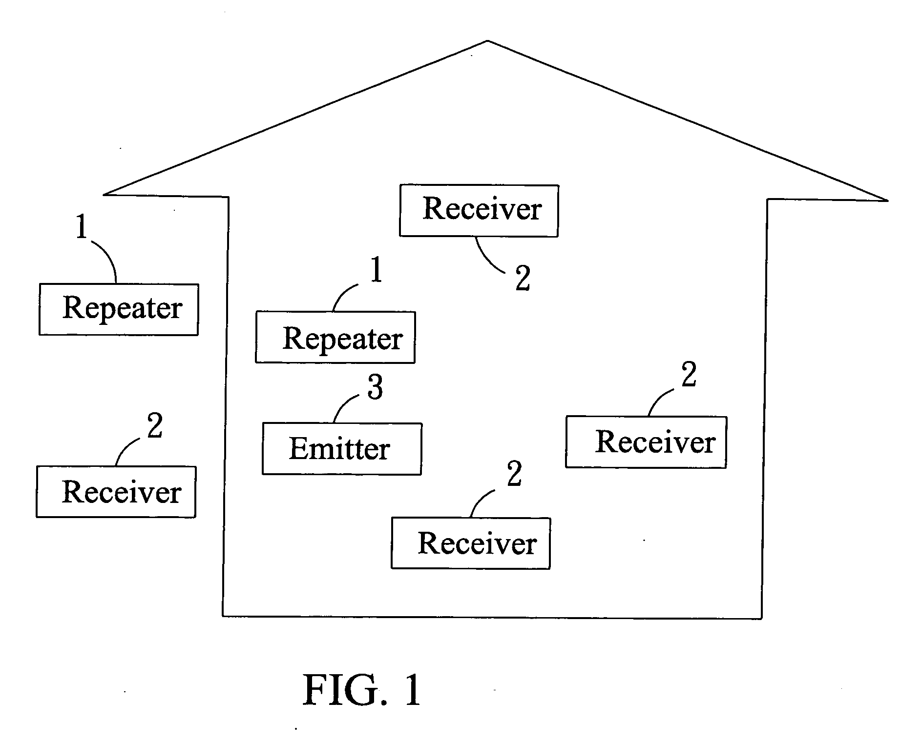
[0027] Referring to FIGS. 1 and 2, an automatic addressing method in accordance with the present invention comprises a plurality of repeaters 1, a plurality of receivers 2 and an emitter 3. The signals that sent out by the emitter 3 are amplified by the repeaters 1, and then received by the receivers 2. The emitter 3 can be a remote controlling device with no battery, the receiver 2 can be an electronic switch, and each electronic switch has a socket for the using of electronic products, however, it is to be noted that the emitter 3 and the receiver 2 are not limited to the above said.

[0028] When the receiver 2 receives a signal, the next signal will be received after a time interval, and the time interval is according to the requirement, for example, two seconds, in order to prevent the receiver 2 from triggering constantly by the transmitted signals of different repeaters 1. In the present embodiment, similarly, when the repeater 1 receives a signal, the next signal will be sent ...


PUM


Abstract

An automatic addressing method, which is applied to communicate a plurality of repeaters in the same area so as to set the respective delayed time, comprising steps describes as follows: (a) The controlling unit of the repeater is inquired whether any other repeaters exist and the numbers of the already existed repeaters through the transmitting unit; (b) The receiving unit of the repeater receives the information so as to know the numbers of the already existed repeaters; (c) The controlling unit of the repeater selects a number that not repeat to that of other repeaters, and sends out the information through the transmitting unit so as to inform other repeaters its adopted number; (d) During a time interval, if the repeater didn't receive the opposing information of other repeaters, then skipped to step (e), if receives any opposing information, it will skip to step (c); (e) The controlling unit stores the number to its memory unit, and later transmits the signals that sent out from the receiving end according to the indicated delayed time of the number.

Description

BACKGROUND OF THE INVENTION [0001] 1. Field of the Invention [0002] The present invention relates to an automatic addressing method, and more particularly to an automatic addressing method and the signal transmitting system of using this method. [0003] 2. Description of the Prior Art [0004] A conventional emitting end sent out signals to a receiving end, a repeater is usually added to avoid dead space or weak signals because of long distance, so that the signals sent out from the emitting end will be amplified by the repeater firstly, and then transmitted to the receiving end so as to receive better signals. [0005] However, if there are several repeaters in the same area simultaneously, the signals sent out from the emitting end will be amplified by the identical repeaters firstly, and then transmitted to the receiving end respectively. At that time, the receiving end will be received multi-signals transmitted by the identical repeaters in a short time, thereby the receiving end wil...

Claims


Application Information

Patent Timeline
Patent Type & Authority Applications(United States)
IPC IPC(8): H04L12/56
CPCH04B7/155
Inventor SHEN, YU-TANGCHEN, ROBERT
Owner FTECH CORP
Features
  • R&D
  • Intellectual Property
  • Life Sciences
  • Materials
  • Tech Scout
  • Unparalleled Data Quality
  • Higher Quality Content
  • 60% Fewer Hallucinations
Learn More