
Preventing unintended communication among power line communication devices associated with different premises power distribution lines of an electric power distribution system

a technology of power distribution system and communication device, applied in wireless systems/telephones, fire alarms, instruments, etc., can solve the problems of insufficient reliability, x-10 technology should not be implemented in life safety devices, and x-10 products are far from reliable, so as to achieve faster communication baud rate, increase transmission power, and significantly more device addresses and message types

Inactive Publication Date: 2005-06-16
GE SECURITY INC
View PDF6 Cites 78 Cited by
  • Summary
  • Abstract
  • Description
  • Claims
  • Application Information

AI Technical Summary

Benefits of technology

[0006] The present invention exhibits the following properties that overcome problems with the existing products that are used for low bandwidth control and alarm reporting applications: much better signal to noise ratios, for much higher reliability; signals can couple across line-cuts in emergency alarm conditions; signals couple across phase wiring, so that no phase bridges are required; a significantly higher number of device addresses and message types are available; communication continues even after complete loss of AC power; full two-way communication protocol incorporates error checking; and acknowledgments of all alarm and control messages for high reliability.
[0008] The first innovation entails transmission of signals using the frequency bands between 2-40 MHz, and does not rely on AC zero crossings to communicate. Use of the higher frequency band (2-40 MHz) allows for faster communication baud rates than those used by X-10 products and for significantly more device addresses and message types. Not relying on AC zero crossings, along with the use of battery back-up in life safety and security equipment, allows the equipment to continue communicating even after complete loss of AC power.
[0009] The second innovation is the achievement of regulatory approval under Federal Communications Commission (FCC) Part 15 as an “intentional radiator.” Power line communication devices have never been listed this way before. However, in the case of life safety equipment, such as smoke detectors or security alarm equipment, it is important to be able to ensure communication even if the power distribution lines become severed or are intentionally cut. Listing a device as an intentional radiator allows for higher transmission power of 10-1000 times more than devices listed as unintentional radiators. This higher power, along with the higher frequencies, also enables signals to easily couple across phases and across severed or broken lines.
[0011] The fourth innovation entails coupling of communications between the two power distribution lines instead of between one power line and ground. Power line communications devices apparently have not been sold in this configuration before. This reduces a number of problems inherent with grounds and meets the criteria for FCC limits on conducted emissions for intentional radiators.

Problems solved by technology

The X-10 technology is incorporated into a wide range of products that meet the low bandwidth requirements, but the X-10 products are far from reliable.
In fact, the reliability is sufficiently unreliable that the X-10 technology should not be implemented in life safety devices like smoke detectors and is usually relegated to lighting control applications.

Method used


Image

  • Preventing unintended communication among power line communication devices associated with different premises power distribution lines of an electric power distribution system
  • Preventing unintended communication among power line communication devices associated with different premises power distribution lines of an electric power distribution system
  • Preventing unintended communication among power line communication devices associated with different premises power distribution lines of an electric power distribution system

Examples


Embodiment Construction

Transceiver Circuitry

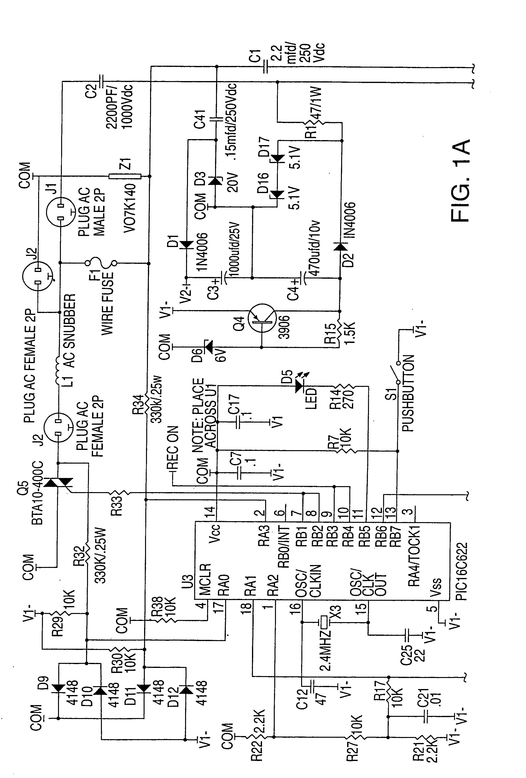
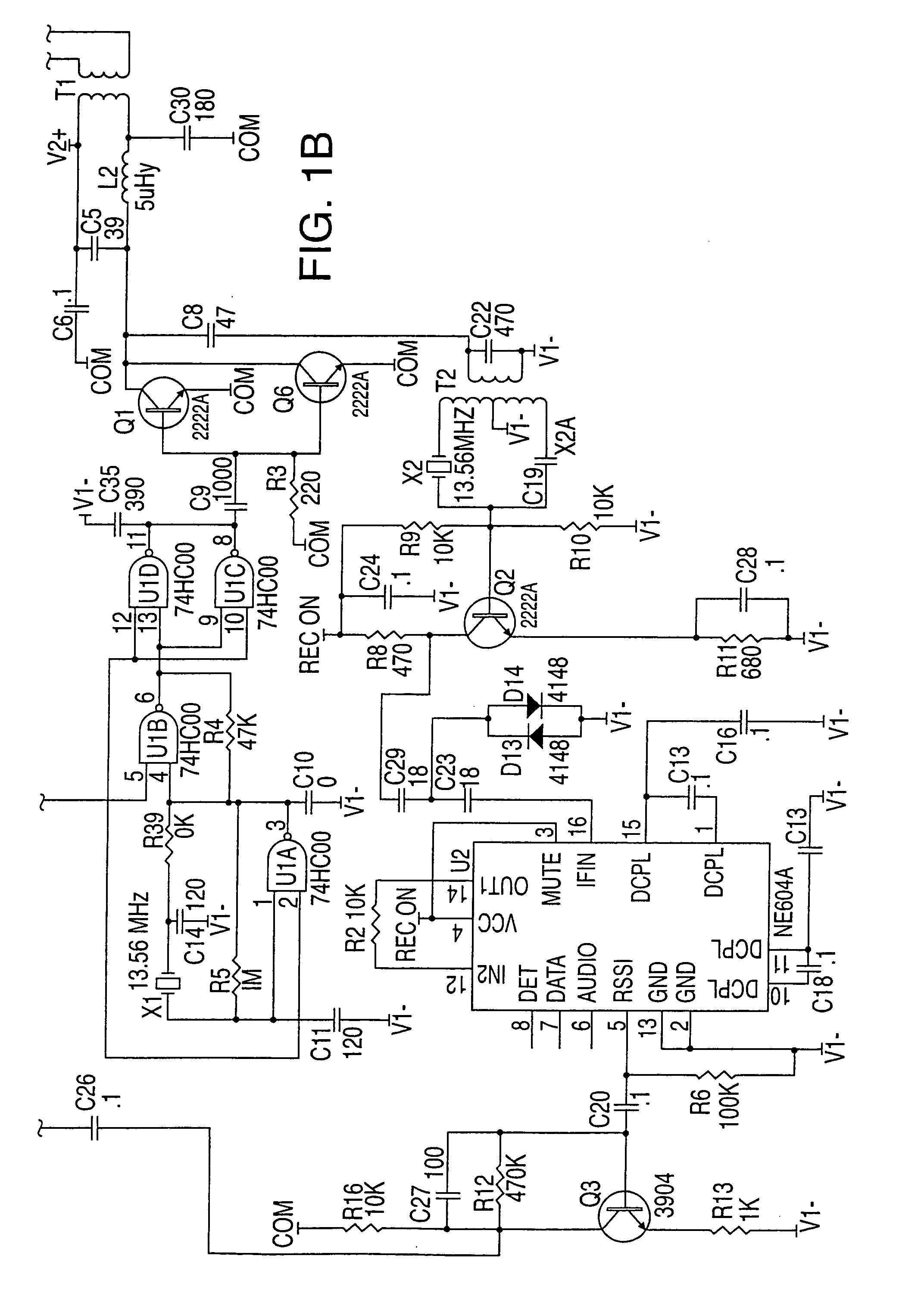
[0024]FIG. 1 is an electrical circuit schematic diagram of a preferred embodiment for a low data bandwidth power line transceiver, which incorporates a number of features designed to keep costs low while enabling highly reliable communications. For example, the transceiver uses one frequency control crystal, tuned to 13.56 MHz, that generates the AM modulated transmission signals. The following is a full description of the circuit operation implemented in a lamp module, which is called a Dialog LC-Lamp Module.

[0025] The Dialog LC-Lamp Module contains six basic circuits combined to provide the following functions: logic and receiver power supply, transmitter power supply, receiver, microprocessor, lamp power control, and transmitter.

[0026] Logic and Receiver Power Supply

[0027] The logic and receiver power supply delivers 5 volt power to the logic, control, receiver and transmitter oscillator-buffer circuits. The 120 volt AC source is reduced to a 10 volt squa...


PUM


Abstract

An electric power line communication system operates with an electric power distribution system to provide through premises power distribution lines highly reliable communication links among power line communication devices electrically coupled or located in proximity to the premises power distribution lines. Each power line communication device associated with a set of premises power distribution lines has an identification address. A master code identifies the power line communication devices as members of a system domain of power line communication devices associated with the set of premises power distribution lines. Association of the master code with the identification addresses renders the member power line communication devices capable of operation without unintended communication with power line communication devices associated with a separate, different set of premises power distribution lines.

Description

RELATED APPLICATIONS [0001] This application is a continuation of U.S. patent application Ser. No. 10 / 229,379, filed Aug. 27, 2002, now U.S. Pat. No. 6,822,555, which is a division of U.S. patent application Ser. No. 09 / 713,675, filed Nov. 15, 2000, now U.S. Pat. No. 6,441,723, which claims benefit of U.S. Provisional Patent Application No. 60 / 165,553, filed Nov. 15, 1999.TECHNICAL FIELD [0002] The present invention relates to a power line communications system and, in particular, to such a system that provides through premises power distribution lines highly reliable communication links among signal receiving devices electrically coupled or located in proximity to the premises power distribution lines. BACKGROUND OF THE INVENTION [0003] Two main companies that have established many years of success with low cost consumer power line communications equipment are X-10 and Phonex. The X-10 products are the current industry standard for low bandwidth communications over power lines for ...

Claims


Application Information

Patent Timeline
Patent Type & Authority Applications(United States)
IPC IPC(8): G08B25/06G08B25/10H04B3/54
CPCG08B25/06G08B25/10H04B3/54H04B2203/5425H04B2203/5437H04B2203/5441H04B2203/5495H04B2203/545H04B2203/5458H04B2203/5479H04B2203/5483H04B2203/5491H04B2203/5445
Inventor MANSFIELD, AMOS ROBBINSMARMAN, DOUGLAS H.
Owner GE SECURITY INC
Learn More