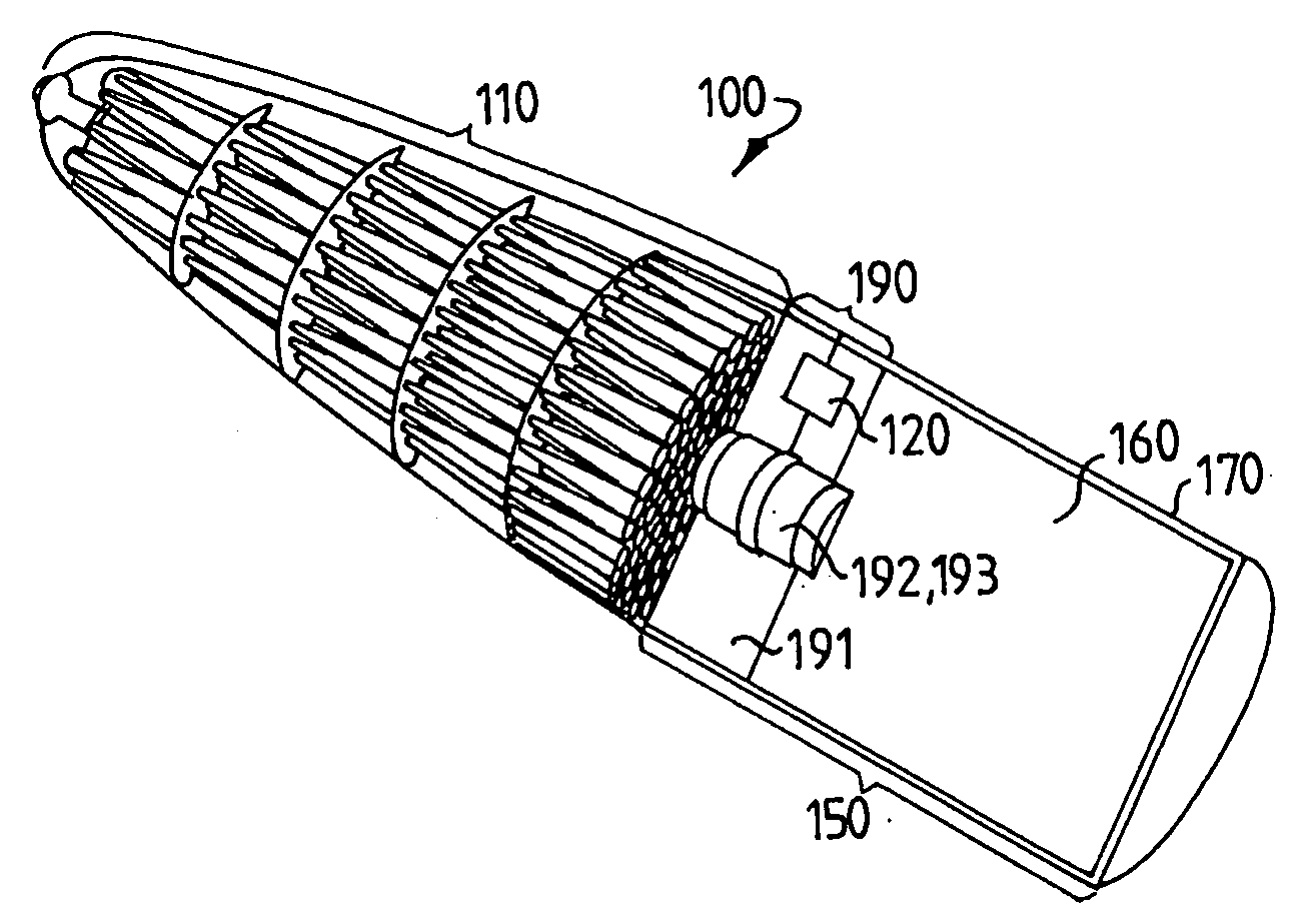
[0044]The
computer device is designed for communication with a combat control
station or other authorized user. The warhead can furthermore be equipped with a
sensor system (not shown). The
sensor system is designed for communication with the
computer device. One
advantage of the invention lies precisely in the fact that the
computer device can be preprogrammed with regard to target selection and desired effect, since the
sensor system might be subject to interference from external sources, which can result in a greater
uncertainty factor. Using a simple command device, a combat control can therefore modify the target selection and / or desired effect at a
late stage in a firing procedure or, as stated, even in flight. In practice the warhead is therefore effective against many different types of target.
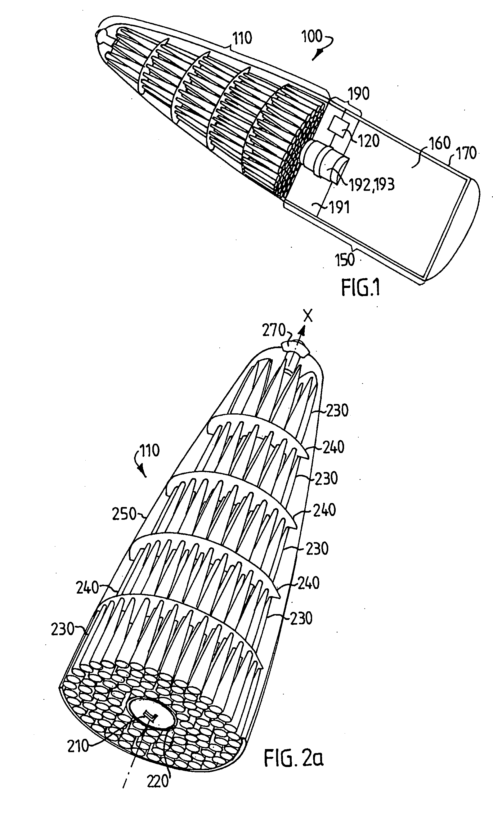
[0045]FIG. 2a shows a main portion according to one embodiment of the invention. The main portion is for the most part rotationally symmetrical about a longitudinal axis x as shown in the drawing. The X-axis is the central axis of the warhead. The main portion comprises an explosive column 210, which extends along its longitudinal axis and is tightly housed in a
sabot 220. Alternatively, there may be plastic or air between the explosive column 210 and the
sabot 220. The explosive column 210 is therefore centrally located in the main portion. The explosive column 210 and the
sabot 220 are rotationally symmetrical about the x-axis.
[0046]The main portion contains aimed projectiles 230 in a number of
layers as shown in the drawing. There may be just one layer. According to one aspect of the invention the main portion comprises five
layers of projectiles 230. The various
layers of projectiles are separated by support rings 240. Should there be five layers of projectiles, there are four support rings arranged in the main portion. The support rings are advantageously made of a
light metal, such as aluminum or aluminum
alloy. Alternatively the support rings may be made of plastics or rubber. The support rings are designed in such a way that they lend stability to the main portion. In particular, the support rings lend stability to the main portion in flight and particularly on
impact with a target. According to one embodiment the support rings are securely attached to the sabot 220. The support rings are therefore circular disks each having a hole therein. According to another embodiment the support rings are tightly joined to the sabot. According to yet another embodiment one or more support rings are firmly attached to the sabot whilst one or more support rings are tightly joined to the sabot
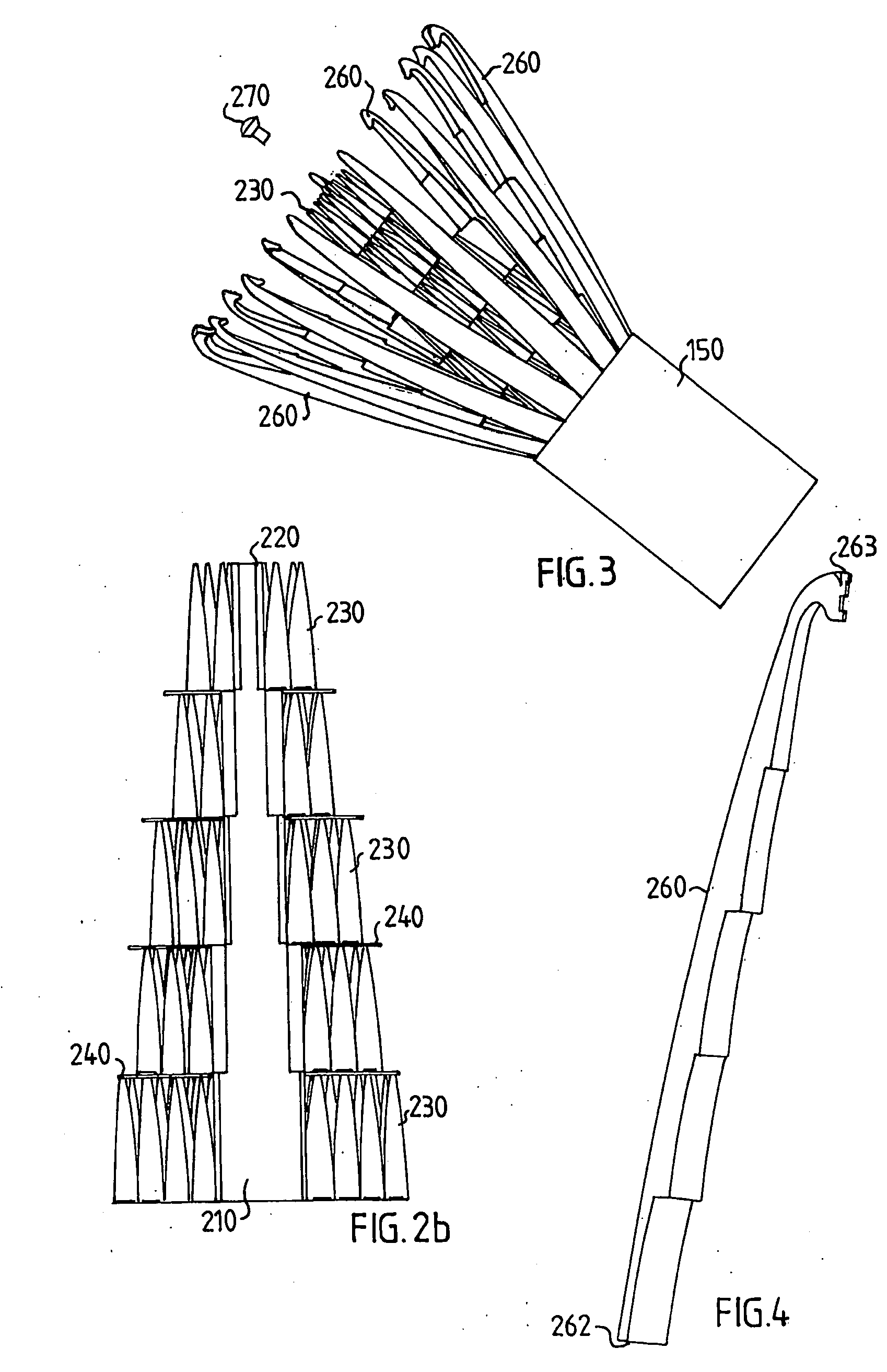
[0047]The main portion is enclosed by an outer shell 250. The outer shell may also be called the casing. The casing 250 is axially segmented in its longitudinal direction. The outer shell may comprise 10 segments 260. According to another embodiment the outer shell comprises 15 segments, but the number of segments may range from 2 to 50. Alternatively the number of segments is greater than 50. Another term for segment used in the description is module. A first end of each segment is detachably fixed to the second module 150. A second end of each segment is fixed to a locking sleeve 270 located at the second end of the main portion, that is to say in the front section of the main portion, as shown in the drawing. The segmented casing is therefore held together by, among other things, the locking sleeve 270 at the second end of the main portion. Alternatively another
fastener may be used. According to one embodiment the locking sleeve is released by the pressure effect caused by
detonation of the explosive column 210. The pressure may be caused, among other things, by expanding explosive gases. According to an alternative embodiment a mechanical rod or spring may be used to release the locking sleeve. The mechanical spring may be controlled electromechanically by the computer device 120. The mechanical rod may be controlled by means of a pyrotechnic charge (not shown ). Once the locking sleeve has been released, the casing can be opened by the pressure of the explosive column. After initial opening the effect of
ambient air can also contribute to further opening in flight. The shell is easily opened and projectiles present in the main portion can be dispersed in a predefined manner. It should be clearly apparent that the casing is designed so that it can withstand high
external pressure, especially on penetrating a target, but can at the same time readily disintegrate when one or more of the casing modules is exposed to a certain
internal pressure, particularly when the explosive column is detonated.
[0048]In their outer section the support rings 240 are each tightly housed in a respective groove arranged in the shell segments 260. The support rings may be composed of aluminum. The support rings may be entirely or partially enclosed in
epoxy resin,
plastic foam or rubber or they may be surface-treated. Each shell segment therefore has at least one groove for each support ring. In a position in which all axial segments enclose the first module, and the locking sleeve is furthermore locked, all support rings are incorporated into the respective grooves of all shell segments on different levels. One of the functions of the support rings is that they exercise a stabilizing effect on the effect part or the entire warhead when it penetrates a target, for example an aircraft
fuselage, since they enter at an angle other than a right angle, that is to say obliquely in relation t o the direction of flight.
[0049]FIG. 2b shows a
schematic, cross-sectional view of a part of a main portion according to one


