Imager linked with image processing station

Inactive Publication Date: 2005-04-19
INTEL CORP
View PDF8 Cites 74 Cited by
  • Summary
  • Abstract
  • Description
  • Claims
  • Application Information

AI Technical Summary

Problems solved by technology

A higher frame rate requires a shorter integration time (and thus also a higher gain), which results in more noise (lower SNR).
Ac

Method used


Image

  • Imager linked with image processing station
  • Imager linked with image processing station
  • Imager linked with image processing station

Examples


Example

[0015]Alternate embodiments of the invention may provide a system, software, and a method for controlling operating parameters of a digital video camera that is coupled with an image processing station via a communication link, although, of course, the invention is not thus limited in scope in this respect.

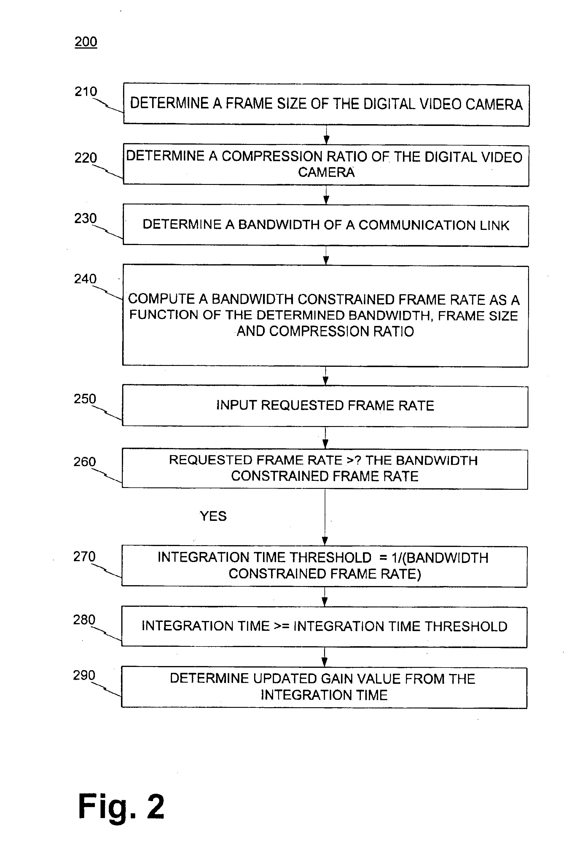
[0016]Briefly the invention determines when the requested video frame rate is larger than the frame rate permitted by the limited bandwidth of the link. If that is so, the invention may set the integration time in such a way that the resulting frame rate is in accordance with a maximum frame rate permitted by the link. The invention may thus optimize the Signal to Noise Ratio (SNR), which also optimizes image quality.

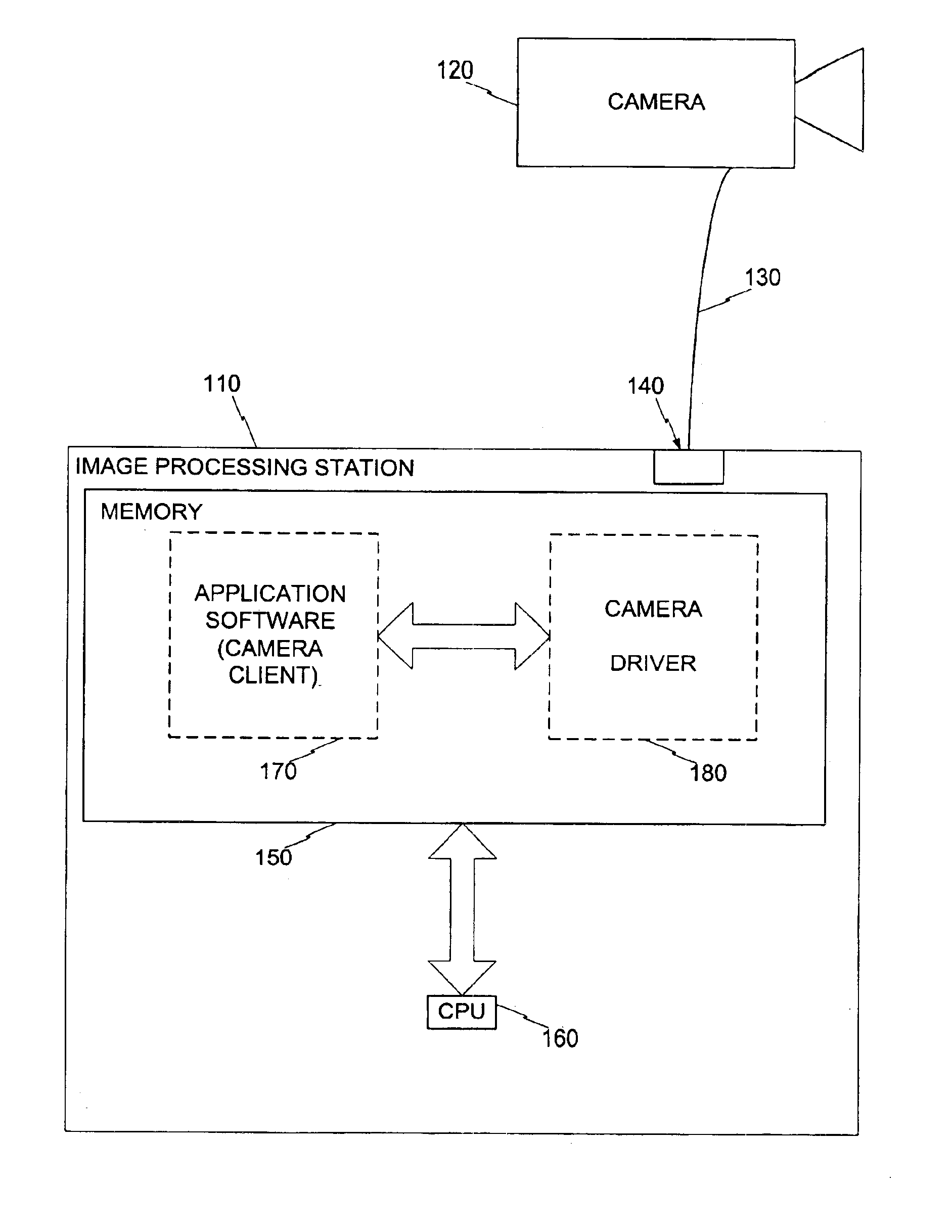
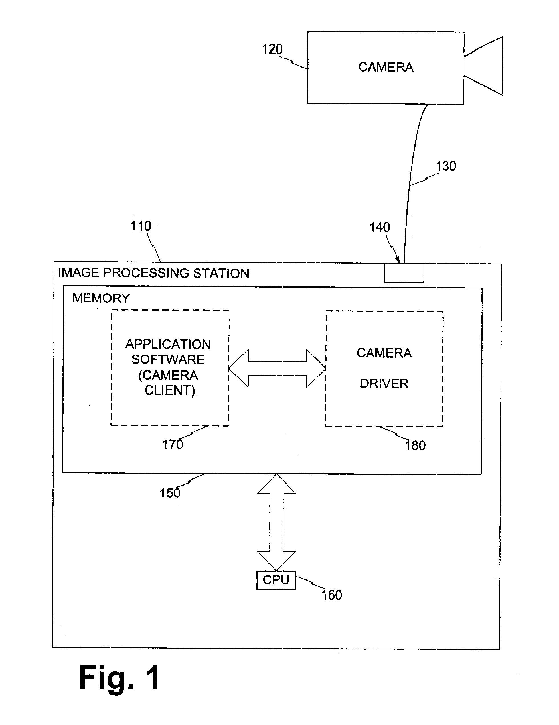
[0017]Referring to FIG. 1, an embodiment of a system according to the invention is now described. The system includes an article such as an image processing station 110. The image processing station 110 can comprise, for example, a special purpose device, or a general...


PUM


Abstract

A digital video camera is coupled with an image processing station by a tether that has a bandwidth. The processing station has a memory with a program that executes instructions. When application software on the station requests a driver on the station to operate the camera at a specific frame rate, the program determines whether the requested frame rate is higher than permitted by the tether bandwidth. If that is so, the program computes a maximum permitted frame rate and an integration time of the pixels of the camera. The integration time causes the camera to produce output video frames at a rate commensurate with the computed bandwidth constrained frame rate, instead of the requested frame rate. The program then adjusts the gain accordingly.

Description

BACKGROUND[0001]1. Field[0002]This disclosure is related to the field of imaging.[0003]2. Background of the Invention[0004]When a digital video camera is aimed at a scene, it generates image data corresponding to the scene. The image data is then processed to produce an image of the scene.[0005]An effort is made to improve the quality of the eventual image. The effort is made by adjusting some of the operating parameters of the digital video camera. Some adjustments are made by the user, and some automatically by the camera.[0006]These operating parameters may include the pixel integration time, the gain, and the frame rate. The camera exposure parameters are the integration time and the gain. These parameters may be interrelated. For example, the integration time is currently determined, at least in part, by the luminance of the scene. If a scene starts becoming darker, the camera might correct for it by increasing the integration time.[0007]There are a number of criteria used to d...

Claims


Application Information

Patent Timeline
IPC IPC(8): H04N7/26H04N7/46H04N5/232
CPCH04N5/23203H04N5/23206H04N19/587H04N19/164H04N19/132H04N23/66
Inventor GAYLORD, JEREMY B.
Owner INTEL CORP
Why Eureka
Try Eureka