Method for improving the coding efficiency of an audio signal

a technology of audio signal and coding efficiency, applied in the direction of code conversion, speech analysis, instruments, etc., can solve the problems of ineffective use of signal, no attention to the relationship between the frequency of the audio signal and its periodicity, and prior art coders, so as to improve the coding accuracy and transmission efficiency of audio signals, the effect of greater accuracy

Inactive Publication Date: 2006-04-27
RPX CORP
View PDF31 Cites 86 Cited by
  • Summary
  • Abstract
  • Description
  • Claims
  • Application Information

AI Technical Summary

Benefits of technology

[0010] In some situations, for example, when an audio signal has a highly periodic nature and varies little over time, lag information alone provides a good basis for prediction of the signal. In this situation it is not necessary to use a high order pitch predictor. In certain other situations, the opposite is true. The lag is not necessarily an integer multiple of the sampling interval. For example, it may lie between two successive samples of the audio signal. In this situation, higher order pitch predictors can effectively interpolate between the discrete sampling times, to provide a more accurate representation of the signal. Furthermore, the frequency response of higher order pitch predictors tends to decrease as a function of frequency. This means that higher order pitch predictors provide better modelling of lower frequency components in the audio signal. In speech coding, this is advantageous, as lower frequency components have a more significant influence on the perceived quality of the speech signal than higher frequency components. Therefore, it should be appreciated that the ability to vary the order of pitch predictor used to predict an audio signal in accordance with the evolution of the signal is highly desirable. An encoder that employs a fixed order pitch predictor may be overly complex in some situations, while failing to model the audio signal sufficiently in others. SUMMARY OF THE EXEMPLARY EMBODIMENTS
[0011] One purpose of the present invention is to implement a method for improving the coding accuracy and transmission efficiency of audio signals in a data transmission system, in which the audio data is coded to a greater accuracy and transferred with greater efficiency than in methods of prior art. In an encoder according to the invention, the aim is to predict the audio signal to be coded frame-by-frame as accurately as possible, while ensuring that the amount of information to be transmitted remains low. The method according to the present invention is characterized in what is presented in the characterizing part of the appended claim 1. The data transmission system according to the present invention is characterized in what is presented in the characterizing part of the appended claim 21. The encoder according to the present invention is characterized in what is presented in the characterizing part of the appended claim 27. The decoder according to the present invention is characterized in what is presented in the characterizing part of the appended claim 30. Furthermore, the decoding method according to the present invention is characterized in what is presented in the characterizing part of the appended claim 38.
[0012] The present invention achieves considerable advantages when compared to solutions according to prior art. The method according to the invention enables an audio signal to be coded more accurately when compared with prior art methods, while ensuring that the amount of information required to represent the coded signal remains low. The invention also allows coding of an audio signal to be performed in a more flexible manner than in methods according to prior art. The invention may be implemented in such a way as to give preference to the accuracy with which the audio signal is predicted (qualitative maximization), to give preference to the reduction of the amount of information required to represent the encoded audio signal (quantitative minimization), or to provide a trade-off between the two. Using the method according to the invention it is also possible to better take into account the periodicities of different frequencies that exist in the audio signal.

Problems solved by technology

Prior art coders have the disadvantage that no attention is paid to the relationship between the frequency of the audio signal and its periodicity.
Thus, the periodicity of the signal cannot be utilized effectively in all situations and the amount of coded information becomes unnecessarily large, or the sound quality of the audio signal reconstructed in the receiver deteriorates.
An encoder that employs a fixed order pitch predictor may be overly complex in some situations, while failing to model the audio signal sufficiently in others.

Method used


Image

  • Method for improving the coding efficiency of an audio signal
  • Method for improving the coding efficiency of an audio signal
  • Method for improving the coding efficiency of an audio signal

Examples


first embodiment

[0030] According to the invention, the pitch predictor order with which the smallest coding error is attained is selected to code the audio signal (block 412). If the coding efficiency measure for the selected pitch predictor is greater than 1, the information relating to the predicted signal is selected for transmission. If the coding efficiency measure is not greater than 1, the information to be transmitted is formed on the basis of the original audio signal. According to this embodiment of the invention, emphasis is placed on minimising the prediction error (qualitative maximization).

[0031] According to a second advantageous embodiment of the invention, a coding efficiency measure is calculated for each pitch predictor order. The pitch predictor order that provides the smallest coding error, selected from those orders for which the coding efficiency measure is greater than 1, is then used to code the audio signal. If none of the pitch predictor orders provides a prediction gain ...

third embodiment

[0032] According to the invention, a coding efficiency measure is calculated for each pitch predictor order and the pitch predictor order that provides the highest coding efficiency, selected from those orders for which the coding efficiency measure is greater than 1, is selected to code the audio signal. If none of the pitch predictor orders provides a prediction gain (i.e. no coding efficiency measure is greater than 1) then advantageously, the information to be transmitted is formed on the basis of the original audio signal. Thus, this embodiment of the invention places emphasis on the maximisation of coding efficiency (quantitative minimization).

fourth embodiment

[0033] According to the invention, a coding efficiency measure is calculated for each pitch predictor order and the pitch order that provides the highest coding efficiency is selected to code the audio signal, even if the coding efficiency is not greater than 1.

[0034] Calculation of the coding error and selection of the pitch predictor order is conducted at intervals, preferably separately for each frame, wherein in different frames it is possible to use the pitch predictor order which best corresponds to the properties of the audio signal at a given time.

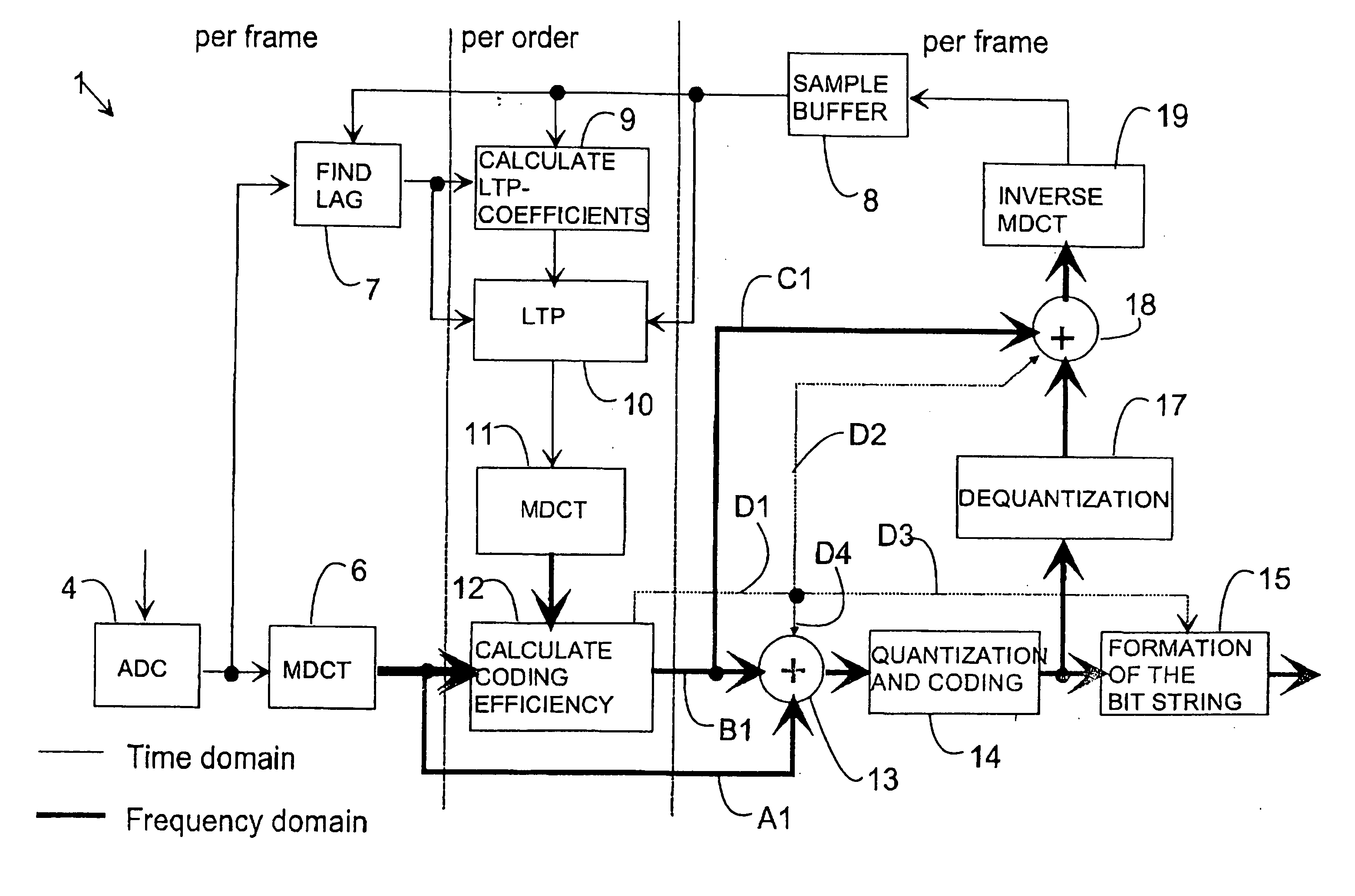
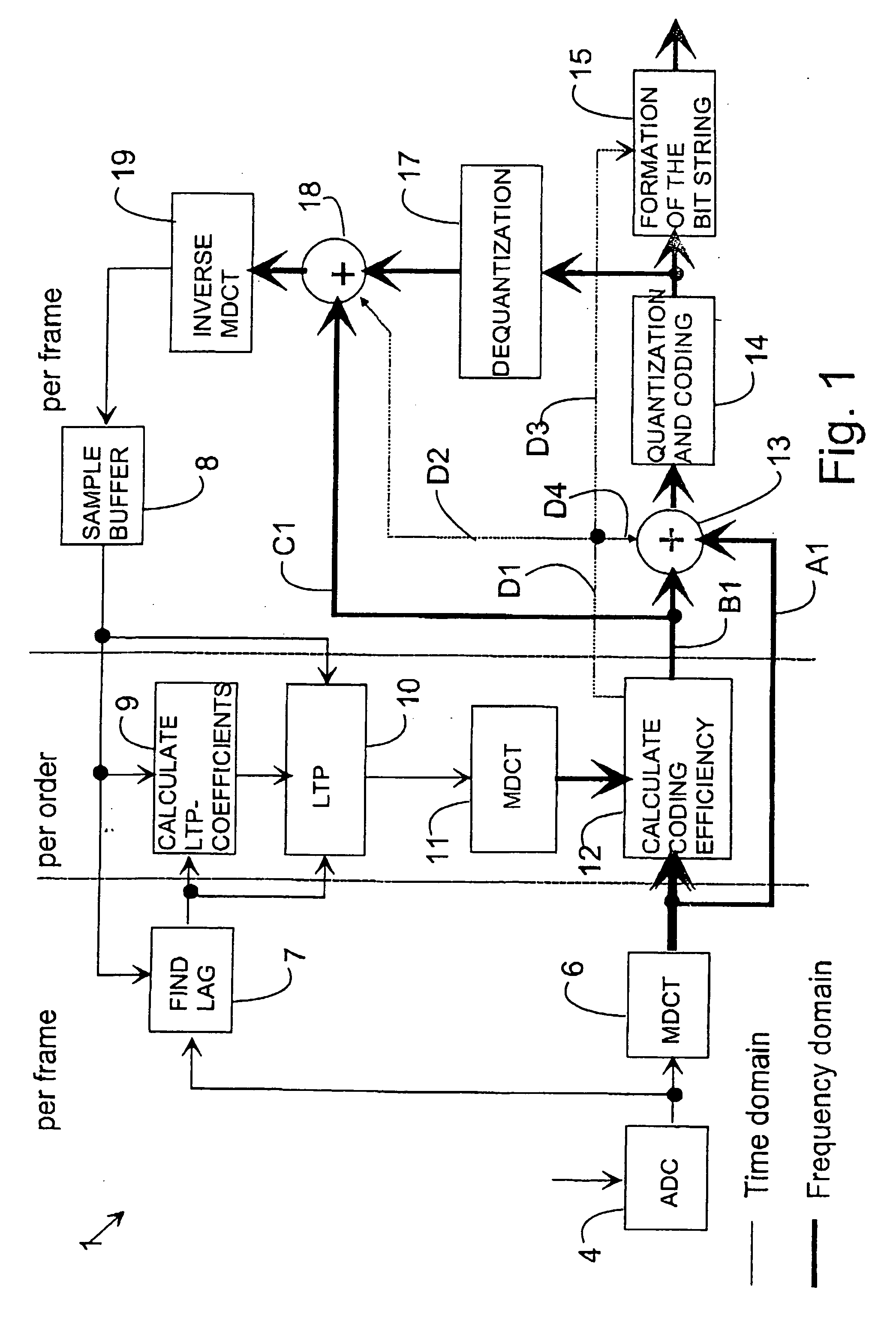
[0035] As explained above, if the coding efficiency determined in block 12 is not greater than one, this indicates that it is advantageous to transmit the frequency spectrum of the original signal, wherein a bit string 501 to be transmitted to the data transmission channel is formed advantageously in the following way (block 415). Information from the calculation block 12 relating to the selected transmission alternative is transf...


PUM


Abstract

Coding an audio signal includes selecting a reference sequence that has the smallest error relative to a sequence of the audio signal, calculating pitch predictor coefficients for the selected reference sequence using one of a set of pitch predictor orders, producing a predicted sequence from the selected reference sequence using the calculated pitch predictor coefficients, and calculating a coding error by comparing the predicted sequence to the sequence to be coded. Coding also includes calculating pitch predictor coefficients for the selected reference sequence, producing a predicted sequence from the selected reference sequence, and calculating a coding error by comparing the predicted sequence to the sequence to be coded, for each of the remaining orders of the set of pitch predictor orders, and using an order from the set of pitch predictor orders that results in the smallest coding error to select a coding method for the sequence to be coded.

Description

[0001] This application is a divisional of co-pending U.S. application Ser. No. 09 / 610,461, filed 5 Jul. 2000, which is incorporated by reference herein in its entirety.BACKGROUND [0002] The disclosed embodiments are directed to methods for coding and decoding an audio signal, an encoder, and a decoder. The embodiments are also directed to a data transmission system and a data structure for transmitting a coded sequence. BRIEF DESCRIPTION OF RELATED DEVELOPMENTS [0003] In general, audio coding systems produce coded signals from an analog audio signal, such as a speech signal. Typically, the coded signals are transmitted to a receiver by means of data transmission methods specific to the data transmission system. In the receiver, an audio signal is produced on the basis of the coded signals. The amount of information to be transmitted is affected e.g. by the bandwidth used for the coded information in the system, as well as by the efficiency with which the coding can be executed. [00...

Claims


Application Information

Patent Timeline
Patent Type & Authority Applications(United States)
IPC IPC(8): G10L11/04G10L19/09G10L19/18H03M7/30H03M7/36H04B14/04
CPCG10L19/09G10L19/18G10L19/08
Inventor OJANPERA, JUHA
Owner RPX CORP
Why Eureka
Try Eureka