Electrical connector to terminate, insulate and environmentally isolate multiple temporary cardiac pacing wires

a technology of electrical connectors and temporary electrical connections, applied in the direction of multi-conductor cable end pieces, coupling device connections, therapy, etc., can solve the problems of not providing 100% electrical insulation connection, not protecting the connection from the environment, and not offering a direct connection to external equipmen

Inactive Publication Date: 2006-11-30
WOJCIECHOWICZ MICHAEL T
View PDF30 Cites 20 Cited by
  • Summary
  • Abstract
  • Description
  • Claims
  • Application Information

AI Technical Summary

Benefits of technology

[0024] Briefly described, the invention comprises an electrical connector for terminating, insulating and environmentally isolating a temporary cardiac pacing wire. The pacing wire may either be the end of the wire itself or, perhaps, a broken off Keith-type needle. The invention includes two primary parts, namely, a conductive adaptor body and an insulated housing. The conductive adaptor body has a contact receiving section, including an aperture therein for receiving the wire or stub end of the Keith-needle, and a plug section for connection to a medical device. An insulated housing or cover includes a first and second, upper and lower, section connected together by a hinge at the ends of the upper and lower sections for surrounding the contact receiving section of the conductive adaptor body and, further, includes a cap connected by a tether or a web to the lower housing. The lower housing includes a pair of posts that engage with a pair of apertures in the upper housing to lock the upper and lower housing together during use. A pair of ribs inside the upper housing cooperate with a rib inside the lower housing to pinch the cardiac pacing ...

Problems solved by technology

Unfortunately, the cables do not provide a 100% electrically insulated connection, nor do they protect the connection from the environment.
It does not offer a direct connection to the external equipment.
This method allows direct connection to the external equipment, however, it does not create an electrically insulated or environmentally isolated connection as the portion of the pin which does not plug into the external equipment is uncovered and often times the uninsulated conductor of the pacing...

Method used


Image

  • Electrical connector to terminate, insulate and environmentally isolate multiple temporary cardiac pacing wires
  • Electrical connector to terminate, insulate and environmentally isolate multiple temporary cardiac pacing wires
  • Electrical connector to terminate, insulate and environmentally isolate multiple temporary cardiac pacing wires

Examples


Embodiment Construction

[0042] During the course of this description like numbers will be used to identify like elements according to the different views which illustrate the invention.

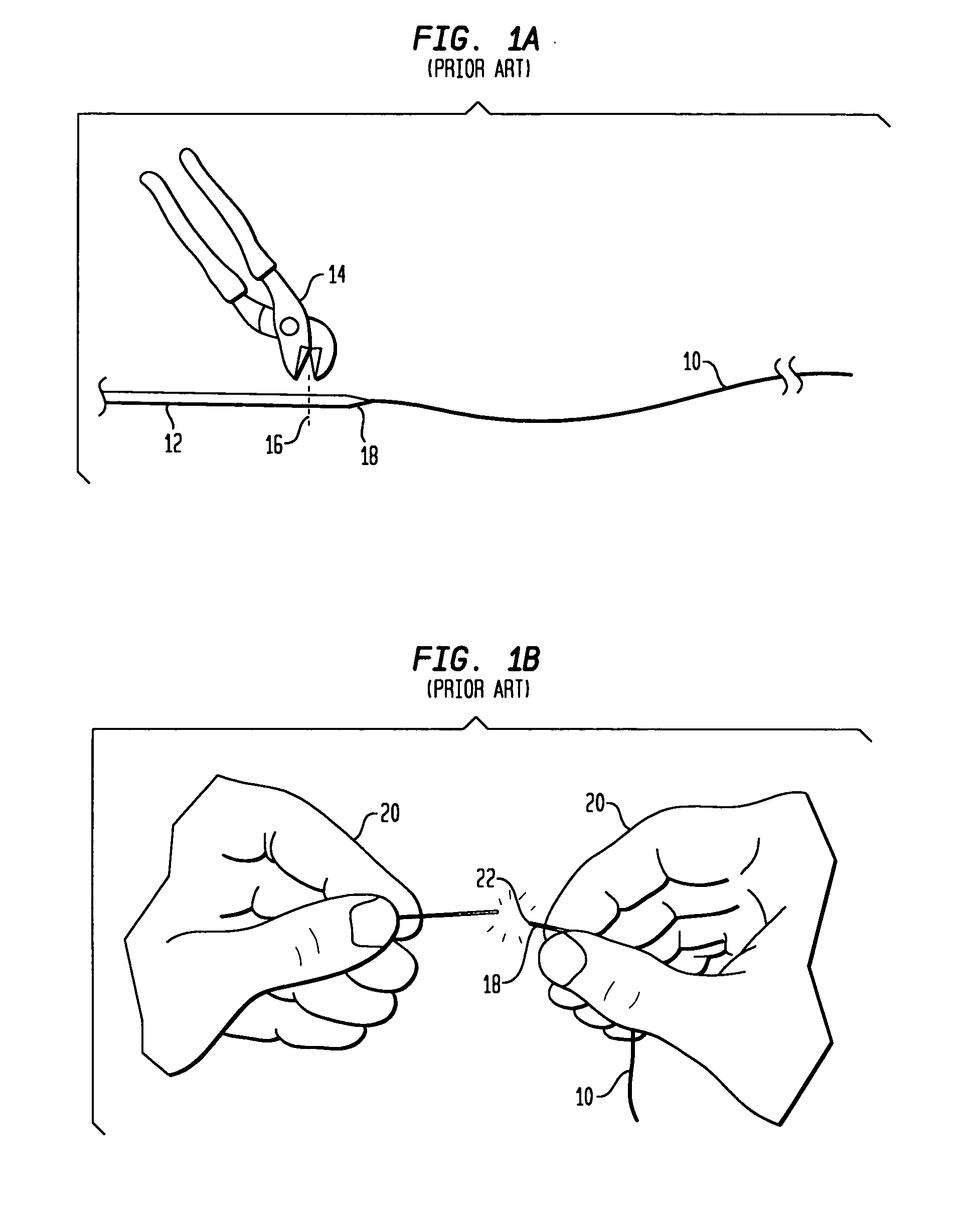
[0043] The present invention comprises an easy-to-use connector which electrically insulates and environmentally isolates the body exterior stub 18 of a temporary cardiac pacing wire 10 and allows it to be directly connected to external equipment without the need for additional cables or interfaces. There is currently no technology which achieves these goals in a satisfactory manner.

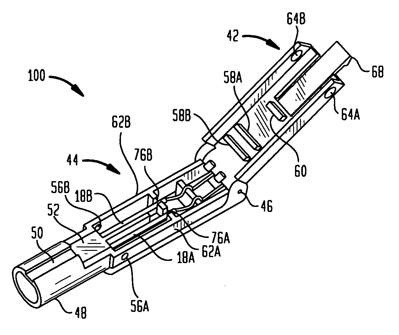
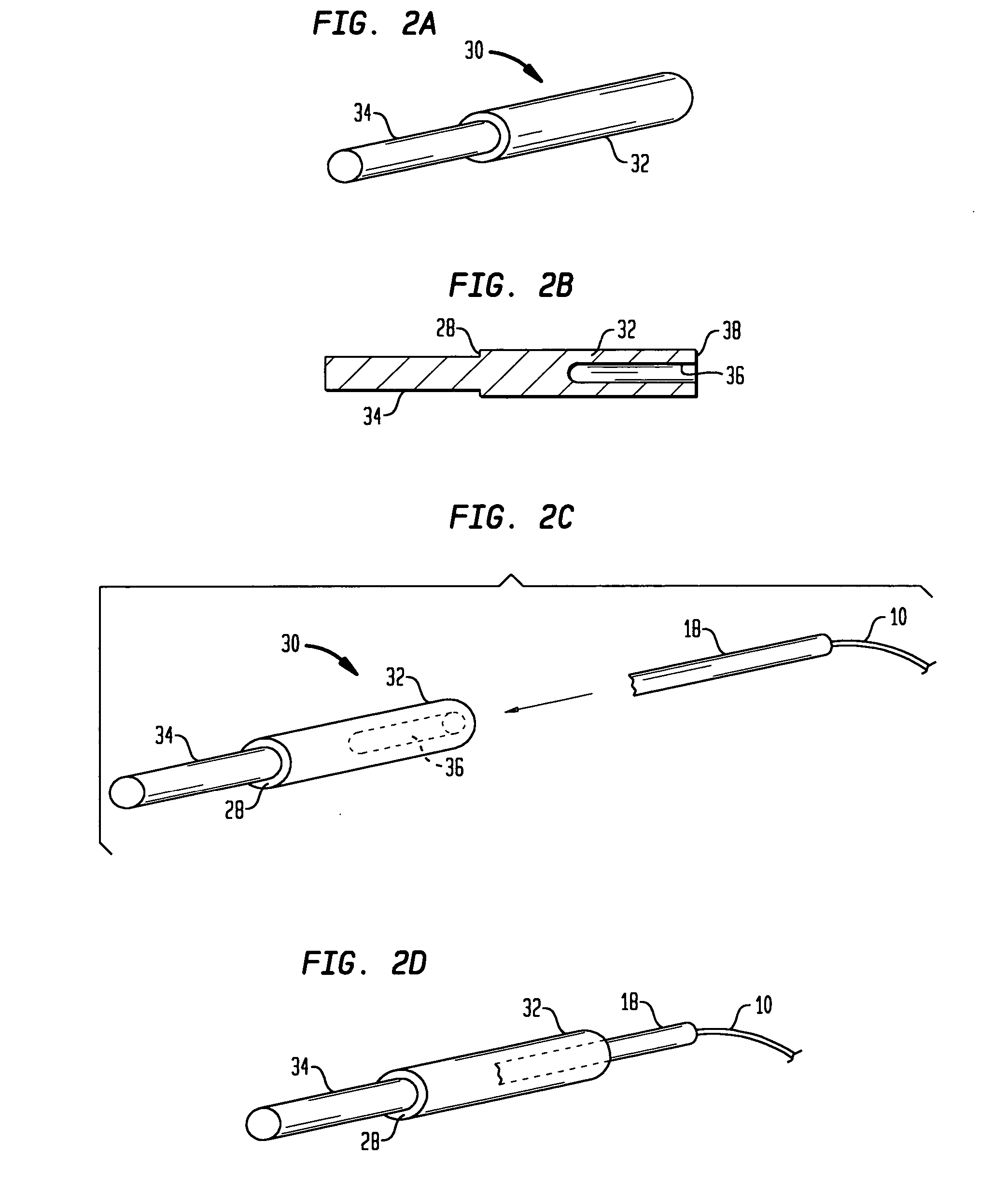
[0044] The present invention consists of two main components, namely, an electrically conductive structure 30 and a housing 40.

[0045] As shown in FIGS. 2A, 2B and 3A the electrically conductive structure of adaptor 30 includes a contact receiving end portion 32 and a plug section 34 separated by a front-facing surface 28. Adaptor 30 also includes a rear-facing surface 38 and an aperture, hole, slot, etc. 36 for accepting the stub 18, or needle...


PUM


Abstract

A connector device, for a temporary cardiac pacing wire, includes a conductive adaptor and a cover section which completely electrically insulates the adaptor and environmentally isolates it. The conductive adaptor comprises a contact receiving end having an aperture therein and a plug portion for plugging into a suitable medical instrument. One or more conductive adaptors are received in a housing comprising a first, or upper section connected by a hinge to a second or lower section. The adaptor is received in the lower section and the plug portion thereof merges inside of a forward barrel portion. A rib in the bottom section cooperates with a pair of ribs on the top section to pinch the pacing wires and hold them in position. A locking post on the inside of the upper cover exerts sufficient frictional stub sections of the electrodes so that they cannot move after the adaptors have been properly positioned inside the lower housing. A cap over the barrel prevents the interior plugs from accidentally contacting an external ground. When the upper section is locked with regard to the lower section, the interior stubs are effectively shielded from exterior strain, electrical contact or dislodgement due to vibration.

Description

CROSS REFERENCE TO RELATED APPLICATIONS [0001] This application claims the priority of provisional U.S. application Ser. No. 60 / 683,944 filed on May 24, 2005 and entitled “An Electrical Connector to Terminate, Insulate and Environmentally Isolate Multiple Temporary Cardiac Pacing Wires in Such a Way to Also Allow Direct Connection to External Pacing or Monitoring Equipment” and U.S. application Ser. No. 11 / 088,586 filed Mar. 24, 2005 entitled “Electrical Connector to Terminate, Insulate and Environmentally Isolate a Temporary Cardiac Pacing Wire” and international application PCT / US04 / 036325 filed on Oct. 29, 2004 and also entitled “Electrical Connector to Terminate, Insulate and Environmentally Isolate a Temporary Cardiac Pacing Wire” all by Michael T. Wojciechowicz, the entire contents and substance of which are hereby incorporated in total by reference.BACKGROUND OF THE INVENTION [0002] 1. Field of the Invention [0003] This invention relates to an electrical connector including a...

Claims


Application Information

Patent Timeline
IPC IPC(8): A61N1/05
CPCA61N1/05H01R11/11H01R13/40H01R13/501H01R13/64H01R13/5829H01R13/5833H01R13/6272H01R13/5224
Inventor WOJCIECHOWICZ, MICHAEL T.
Owner WOJCIECHOWICZ MICHAEL T
Why Eureka
Try Eureka