Nucleus replacement securing device and method

a nucleus and securing device technology, applied in the field of nucleus replacement securing, can solve the problems of reducing the cushioning ability, degenerative effects, pain in the back and lower extremities,

Inactive Publication Date: 2006-11-30
THEKEN SURGICAL LLC
View PDF1 Cites 58 Cited by
  • Summary
  • Abstract
  • Description
  • Claims
  • Application Information

AI Technical Summary

Benefits of technology

[0008] In a first embodiment, an alignment device mounts to the posterior aspect of the spine and drills curved holes down through the pedicle of the segment and into the disc space of the level. At the adjoining level, holes are also drilled in the pedicle into the adjoining disc space so that each exit of the curved hole meet at a single disc space. A suture is then threaded through the first curved hole, to the disc space, then is extracted from the disc space to the posterior. The suture is threaded through a nucleus replacement, or through the covering around a nucleus replacement, and then back into the disc space where it is pulled through the second hole and out to the pedicle. Having a suture that goes through each pedicle and around the nucleus replacement allows the suture to be pulled from both ends to urge the nucleus replacement into position still secured to the suture. Plugs are then inserted into the pedicle and attached to the suture so as to fix the suture in place. The suture is then cut keeping the nucleus replacement in a fixed position within the disc space. The suture holds the nucleus replacement secured to a fixed position after it has been guided into place. While the nucleus replacement may be permitted a certain amount of movement in certain embodiments, it is secured within the disc space so as not to be expelled therefrom.
[0009] In a second embodiment, the ends of the suture expelled from both pedicles are joined with a tension band between the two pedicles that can act as a further stabilizing effect to the segment.
[0010] In a third embodiment, the pedicles of the same vertebra are used as access into the adjacent disc space. The two sutures or pathways are through the superior vertebral end place of the vertebra. This allows preservation of the entire periphery of the annulus fibrosis if the nucleus replacement is collapsible and can be inserted through the pedicle.

Problems solved by technology

Over time, these discs have a tendency to loose water which in turn reduces their cushioning ability.
Along with a reduced hydraulic nature, the disc loses its ability to maintain disc height and bear loads resulting in a cascade of degenerative effects.
As this degenerative process continues, a disc herniation involving bulging or expelling of disc material can occur leading to pain to the back and lower extremities.
When the pain generating disc is removed, the disc space will collapse resulting in instability and further trauma to surrounding tissue and ensuing pain.
This process is, however, believed to place undo stress on other vertebral levels as they compensate for the lack of motion, in turn potentially leading to premature failure of those other discs as well.
Current methods and concepts have undergone human clinical trials to little success and suffers from an inability to access, place, and then finally secure the nucleus replacement in place.
Several attempts at human trials have even resulted in expulsion of these devices out of the disc space.

Method used


Image

  • Nucleus replacement securing device and method
  • Nucleus replacement securing device and method
  • Nucleus replacement securing device and method

Examples


Embodiment Construction

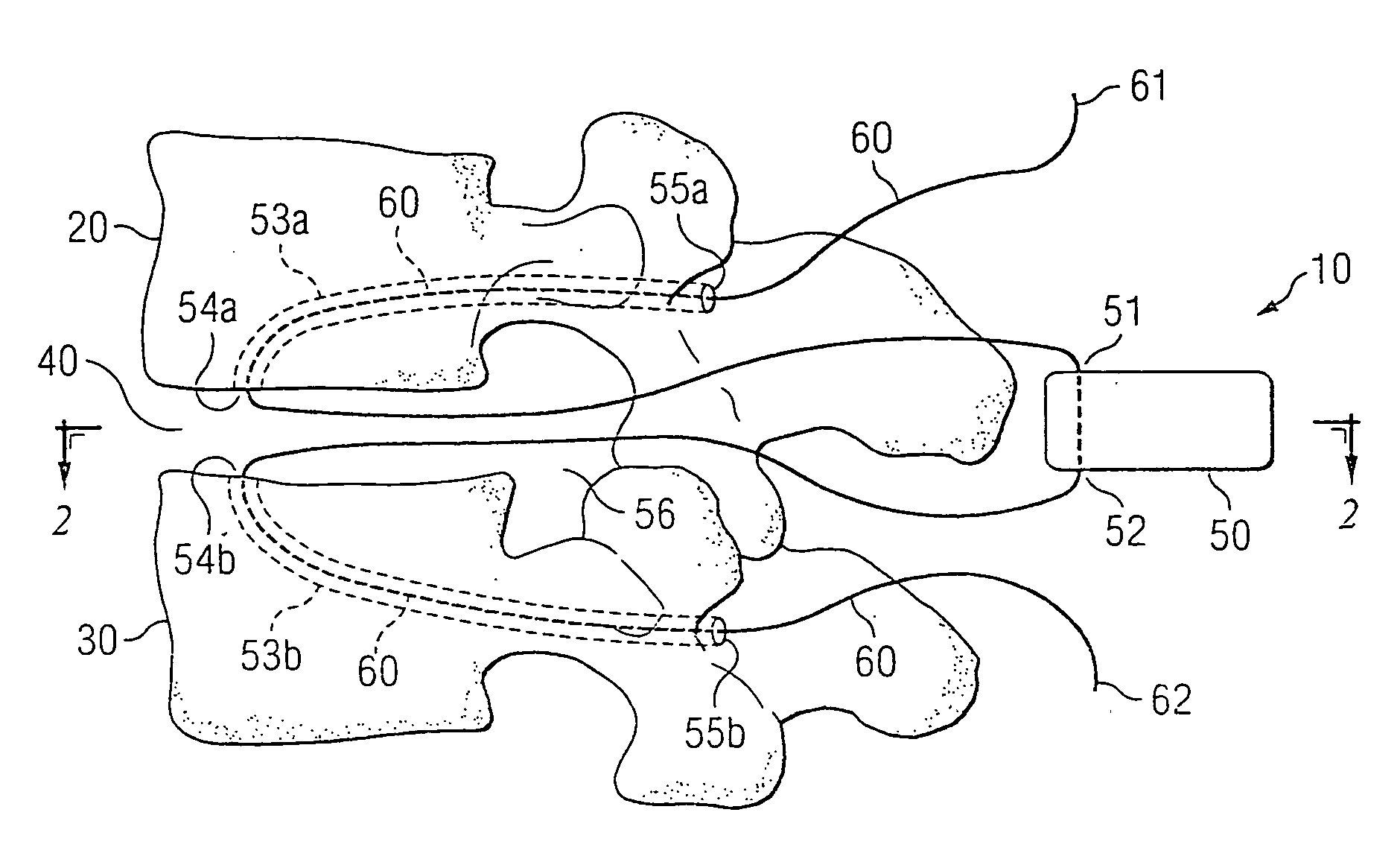
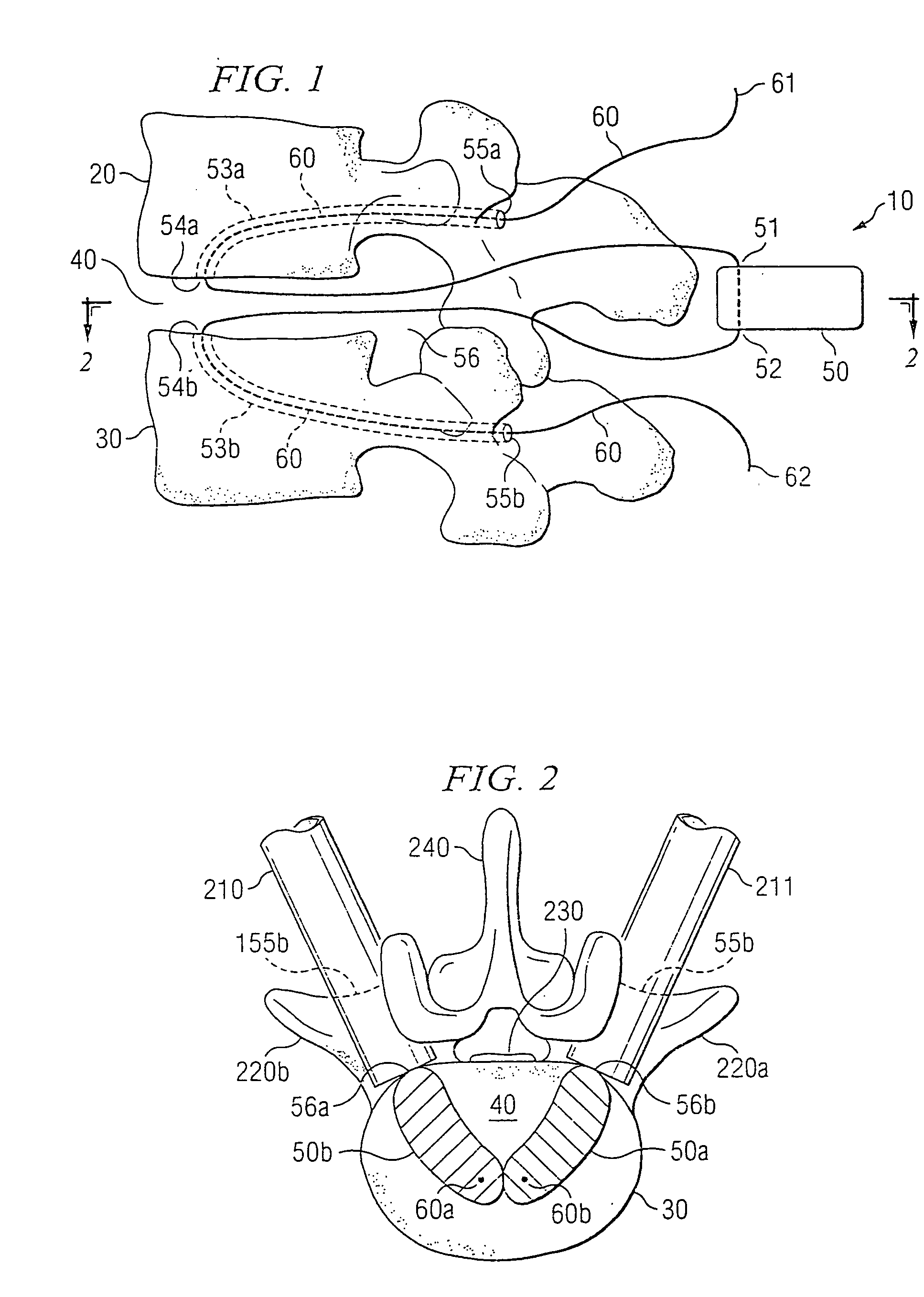
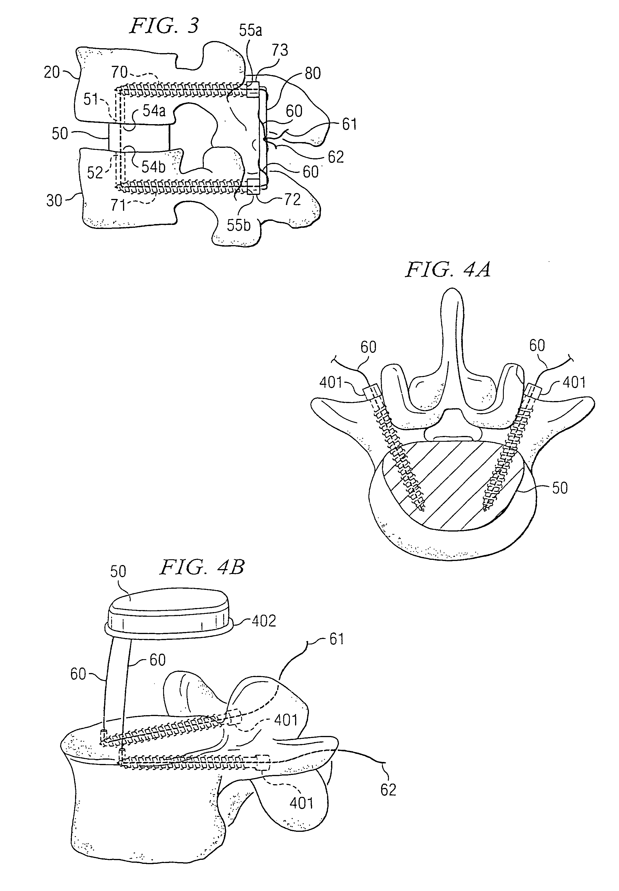
[0019] Turning now to FIG. 1, vertebral segment 10 includes superior vertebral level 20 and inferior vertebral level 30. These are shown as level L4 and level L5 in this example, however the concepts taught herein could be used at any level in the spine. A description of a first embodiment of a device and method for using the device for inserting and securing a replacement nucleus within a disc space is now described in connection with vertabral segment 10 of FIG. 1. FIG. 1 shows a nucleus replacement 50 which must be inserted into the disc space 40. To assist this endeavor, two holes 53a and 53b are drilled into the vertebral levels 64, 65 using fluoro to track a cutting bit in its path, starting from the opening of the pedicles 55a, 55b and extending on a curved path to the disc space 40 as shown.

[0020] After the holes are drilled, a suture 60 starting with end 62 is passed through the L4 pedicle opening 55a, through the first tunnel 53a, and into the disc space 40 passing the en...


PUM


Abstract

There is disclosed systems and methods for spinal nucleus replacement by constructing channels through vertebral segments on either side of an area into which the spinal nucleus is to be positioned, the channels running from a channel end outside of the area to a channel end abutting the area. One end of a suture is inserted into the outside channel end of a first one of the channels and passed through the first channel and into the area and out of the area through the second channel until it emerges from the second channel. The suture is then used to pull the nucleus into the area.

Description

RELATED APPLICATIONS [0001] This application is a divisional of U.S. patent application Ser. No. 11 / 007,648 filed Dec. 7, 2004 and entitled “Nucleus Replacement Securing Device and Method”, which claims priority to U.S. Provisional Patent Application Ser. No. 60 / 527,855 entitled “Nucleus Replacement Securing Device and Method”, filed Dec. 8, 2003, the disclosure of which is hereby incorporated herein by reference.TECHNICAL FIELD [0002] This invention relates to securing of a nucleus replacement and more specifically, to assistance in placing, stabilizing, and securing of a nucleus replacement in the disc space between two adjacent vertebrae from a posterior, posterolateral, or lateral approach. BACKGROUND OF THE INVENTION [0003] Spinal discs are the primary mechanical cushion for the vertebral column and permit controlled motion between the vertebral segments. Over time, these discs have a tendency to loose water which in turn reduces their cushioning ability. Along with a reduced h...

Claims


Application Information

Patent Timeline
Patent Type & Authority Applications(United States)
IPC IPC(8): A61F2/44A61B17/04A61B17/84A61F2/00A61F2/30A61F2/46
CPCA61B17/0401A61F2310/00029A61B2017/0414A61B2017/0458A61F2/442A61F2/4611A61F2002/30133A61F2002/30235A61F2002/30462A61F2002/30909A61F2002/444A61F2002/448A61F2220/0075A61F2230/0015A61F2230/0069A61B17/842
Inventor MCAFEE, PAUL
Owner THEKEN SURGICAL LLC
Why Eureka
Try Eureka