

Electric driving device for a valve
- Summary
- Abstract
- Description
- Claims
- Application Information
AI Technical Summary
Benefits of technology
Problems solved by technology
Method used
Image

Examples
first embodiment
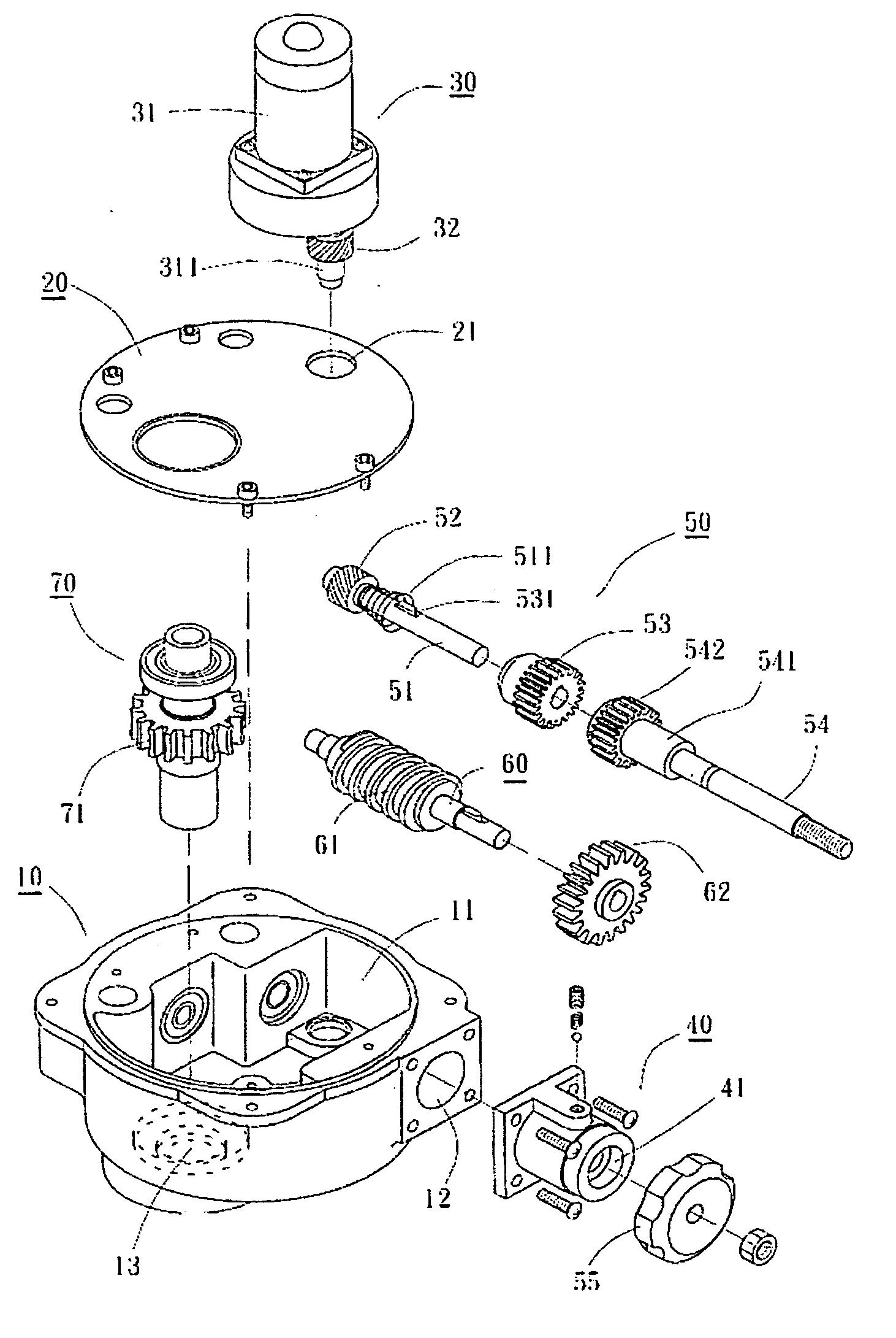
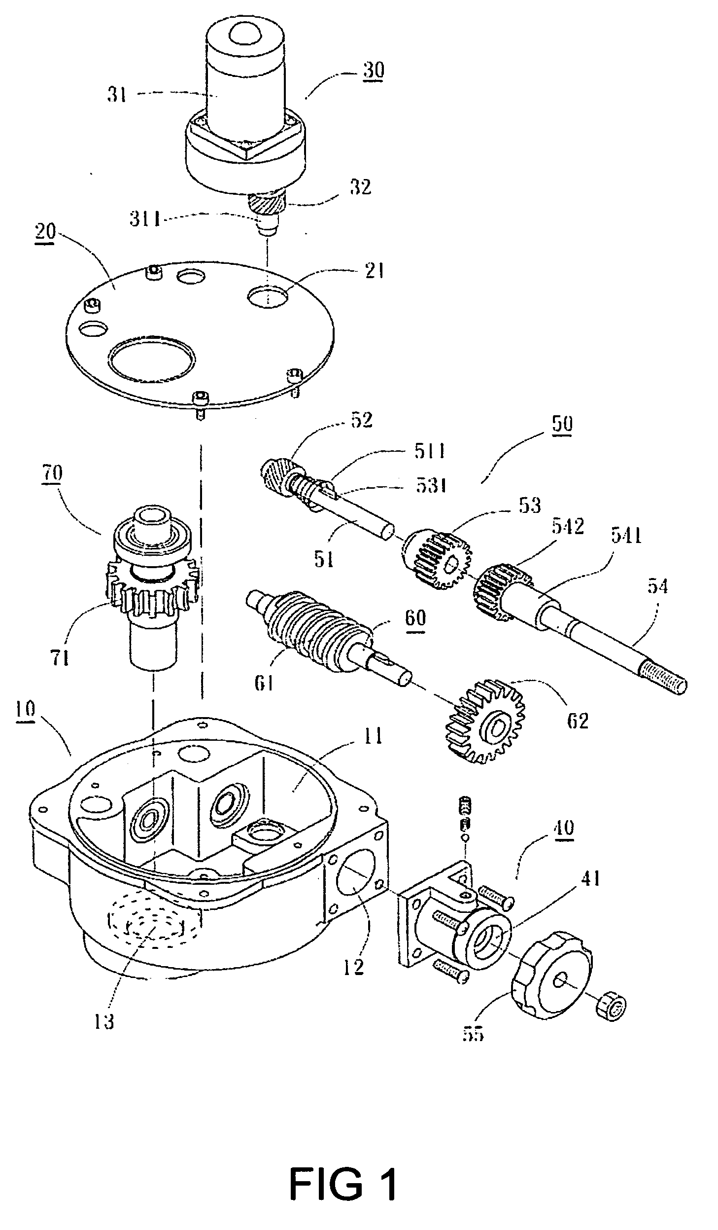
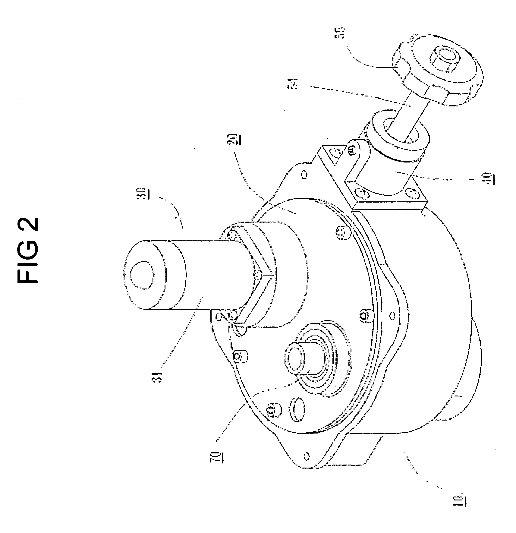
[0017] Referring to FIGS. 1 to 4, an electric driving device for a valve according to the present invention includes a lower casing member 10, a cover plate 20, a driving unit 30, a cylindrical part 40, a control unit 50, a third rod member 60 and a fourth rod member 70.
[0018] The lower casing member 1 has a containing space 11 therein with an open top, a through hole 12 being disposed at the right lateral wall thereof and an outlet 13 at the left bottom thereof.
[0019] The cover plate 20 is used for closing the open top of the lower casing member 1. A cover hole 21 is provided at the cover plate 20.
[0020] The driving unit 30 further has an electric mover 31. The electric mover 31 is disposed above the cover hole 21 and a speed reduction gear train (not shown) is provided under the electric mover 31. The output shaft 311 of the speed reduction gear train passes through the cover hole 21 with the lower end thereof being movably attached to the bottom wall of the lower casing 10. A f...
second embodiment
[0028] Referring to FIGS. 5 to 10, the present invention is illustrated. The difference of the present embodiment is described hereinafter.
[0029] The cover plate 20 provides a rectangular opening 22 corresponding to the rear section of the third rod 60. A flat member 23 is disposed a specific distance above the rectangular opening 22 with a cutout corner 231 corresponds to the opening 22. A micro switch 24 is provided on the flat member 23 next to the cutout corner 231.
[0030] The fifth gear 61 is slidably attached to the third rod 60 with a key 611 and a second elastic member 63 is added between the fifth gear 61 and the sixth gear 62. A third elastic member 64 is added between the fifth gear 61 and the rear wall of the containing space 11. The second and third elastic members 53, 64 shown in the figures are springs. Further, a safety arm 65 is provided next to an end of the fifth gear 61 with the upper end thereof passing through the opening 22 and disposed between the micro switc...
PUM
 Abstract
Description
Claims
Application Information