Multi-Blade Curette Tool

a multi-blade, curette technology, applied in the field of curette, can solve the problems of time-consuming and relatively inefficient curetting process, unfavorable patient care, and uneven pressure on the cavity walls

Active Publication Date: 2006-12-07
SPINAL ELEMENTS INC
View PDF6 Cites 31 Cited by
  • Summary
  • Abstract
  • Description
  • Claims
  • Application Information

AI Technical Summary

Benefits of technology

[0006] The following detailed description of preferred embodiments of the invention will be better understood when read in conjunction with the appended drawings. For the purpose of illustrating the invention, there are shown in the drawings embodiments which are presently preferred. It should be understood, however, that the invention is not limited to the precise arrangements and instrumentalities shown.

Problems solved by technology

In operation, ring curettes do require some tilting, which leads to uneven pressure on the cavity walls.
The curetting process using known curettes tends to be time-consuming and relatively inefficient.

Method used


Image

  • Multi-Blade Curette Tool
  • Multi-Blade Curette Tool
  • Multi-Blade Curette Tool

Examples


Embodiment Construction

[0027] Certain terminology is used in the following description for convenience only and is not limiting. The words “right”, “left”, “lower”, and “upper” designate directions in the drawing to which reference is made. The words “inwardly” and “outwardly” refer direction toward and away from, respectively, the geometric center of the multi-blade curette and designated parts thereof. The terminology includes the words above specifically mentioned, derivatives thereof and words of similar import. Additionally, the word “a”, as used in the claims and in the corresponding portions of the specification, means “at least one.”

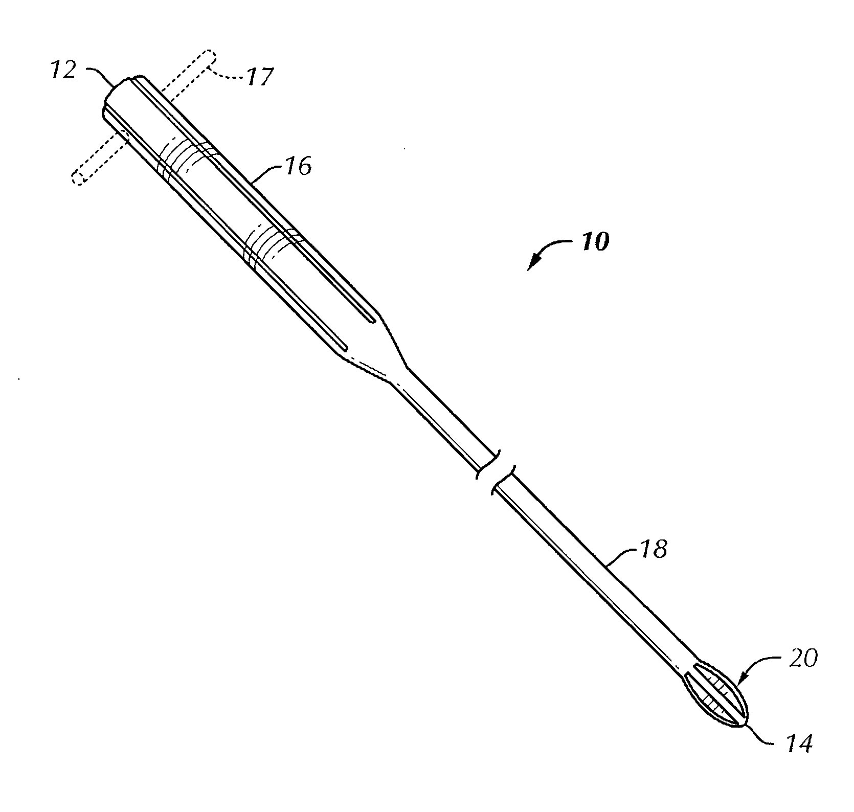
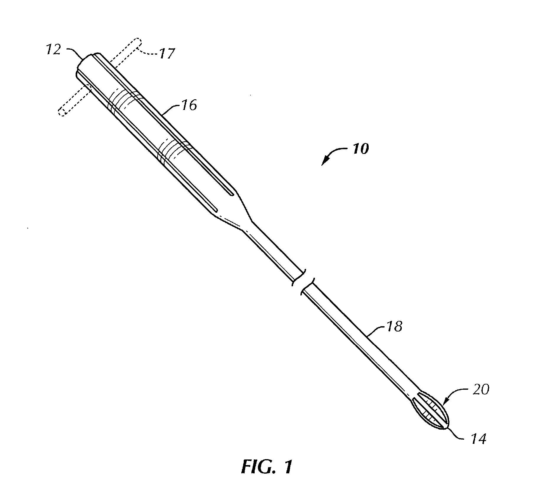
[0028] Referring to the drawings in detail, wherein like reference numerals indicate like elements throughout, and with initial reference to FIG. 1, there is shown a multi-blade curette tool 10 (or “curette 10”) in accordance with a preferred embodiment of the present invention. The curette 10 is adapted for use in spinal surgery. The curette 10 comprises an elongated ...


PUM

PropertyMeasurementUnit
diameteraaaaaaaaaa
lengthaaaaaaaaaa
lengthaaaaaaaaaa

Abstract

A multi-blade curette tool for use in spinal surgery. The curette tool includes an elongated member having a first end and a second end. A handle is disposed at the first end. A curette head is disposed at the second end. The curette head is generally tapered toward the first end and the second end. The curette head includes a convexly-shaped and generally tapered nose portion, a base portion, and a plurality of blades. Each blade extends between the base portion and the nose portion, and each of the plurality of blades is provided with at least one cutting element. A drive stem connects the handle and the curette head. At least one cutting element of each blade is adapted to remove spinal disk material upon rotation of the curette tool in at least one direction.

Description

CROSS REFERENCE TO RELATED APPLICATIONS [0001] This application claims priority to U.S. Provisional Application No. 60 / 687,840, filed Jun. 6, 2005, entitled “Multi-Blade Curette with Convex Profile.”BACKGROUND OF THE INVENTION [0002] Embodiments of the present invention relate to a curette used in spinal surgery on animals and humans, and more particularly to a multi-blade curette tool for use in spinal surgery. [0003] It is known to use curettes in surgical and other medical procedures to debride or clean spaces or cavities in the body (e.g., ears, uterus, sinuses, cavities within skeletal structures, and spinal disk spaces). Early curettes were simple spoon-like cups. It is known to include an angled section in such spoon-like curettes to facilitate the curetting process when an opening through which the curette is inserted is smaller than the cavity to be cleaned. Ring curettes are also known. Ring curettes have two blades which contact walls of the cavity. Ring curettes allow cl...

Claims


Application Information

Patent Timeline
Patent Type & Authority Applications(United States)
IPC IPC(8): A61B17/22
CPCA61B17/1671A61B17/320708Y10T408/34A61B2017/320008Y10T407/19A61B2017/00261
Inventor ECKMAN, WALTER W.
Owner SPINAL ELEMENTS INC
Why Eureka
Try Eureka