Bipod assembly with terrain-gripping end effecters

a technology of end effecters and bipods, which is applied in the direction of machine supports, dismountable cabinets, ammunition loading, etc., can solve the problems of unfavorable shooting range adjustment, inconvenient and difficult use, and inability to hold a firearm consistently in a set position without wavering,

Inactive Publication Date: 2006-12-14
KENGS FIREARMS SPECIALTY
View PDF23 Cites 80 Cited by
  • Summary
  • Abstract
  • Description
  • Claims
  • Application Information

AI Technical Summary

Benefits of technology

[0019] The resulting attachment of the clamp assembly to the forearm stock provides a quick and easy attachment of the bipod to the firearm (or some other instrument requi

Problems solved by technology

Most shooters are not able to hold a firearm consistently in a set position without wavering, especially after the onset of fatigue resulting from strain on the shooter due to the size and weight of the firearm.
Early bipod and tripod supports typically were somewhat crude strands that generally were bulky, inconvenient and difficult to use and typically were not easily adjustable.
A problem with conventional bipods has been the tendency of the bipod's feet (or distal end surfaces) to slide along or sink into the ground or other soft supporting surface, unintentionally altering the shooter's point of aim.
Additionally, most bipods are not designed for quick and easy attachment and release of the bipod from the firearm s

Method used


Image

  • Bipod assembly with terrain-gripping end effecters
  • Bipod assembly with terrain-gripping end effecters
  • Bipod assembly with terrain-gripping end effecters

Examples


first embodiment

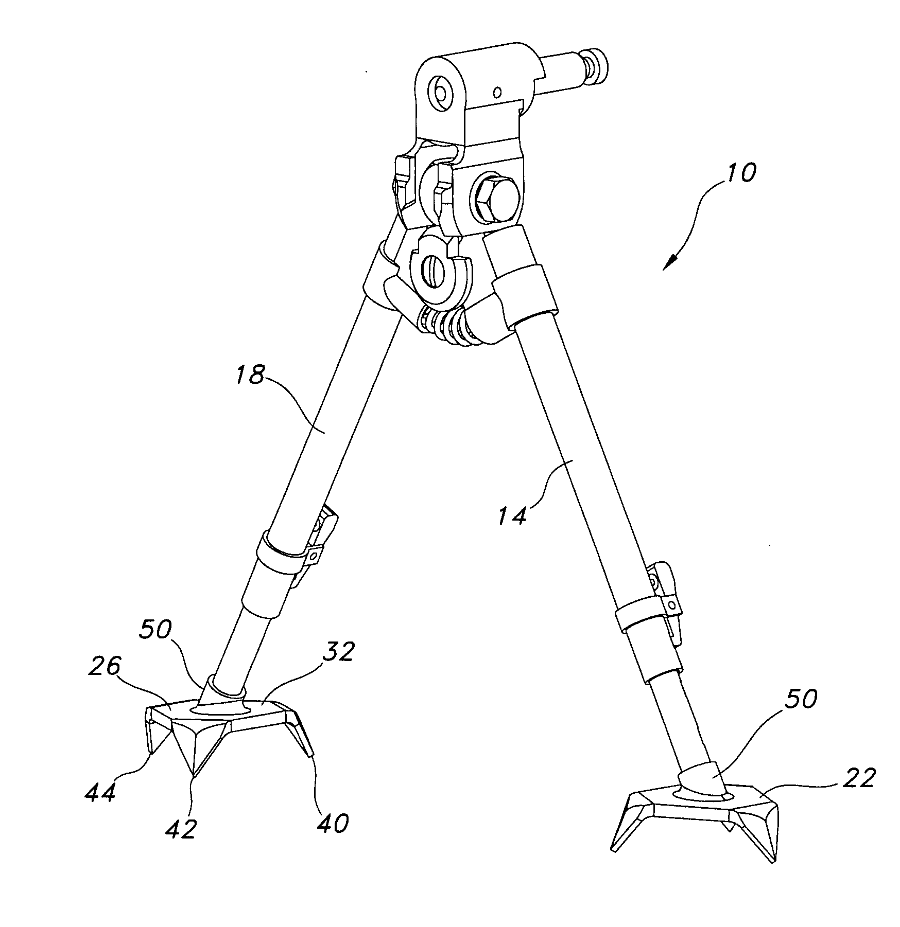
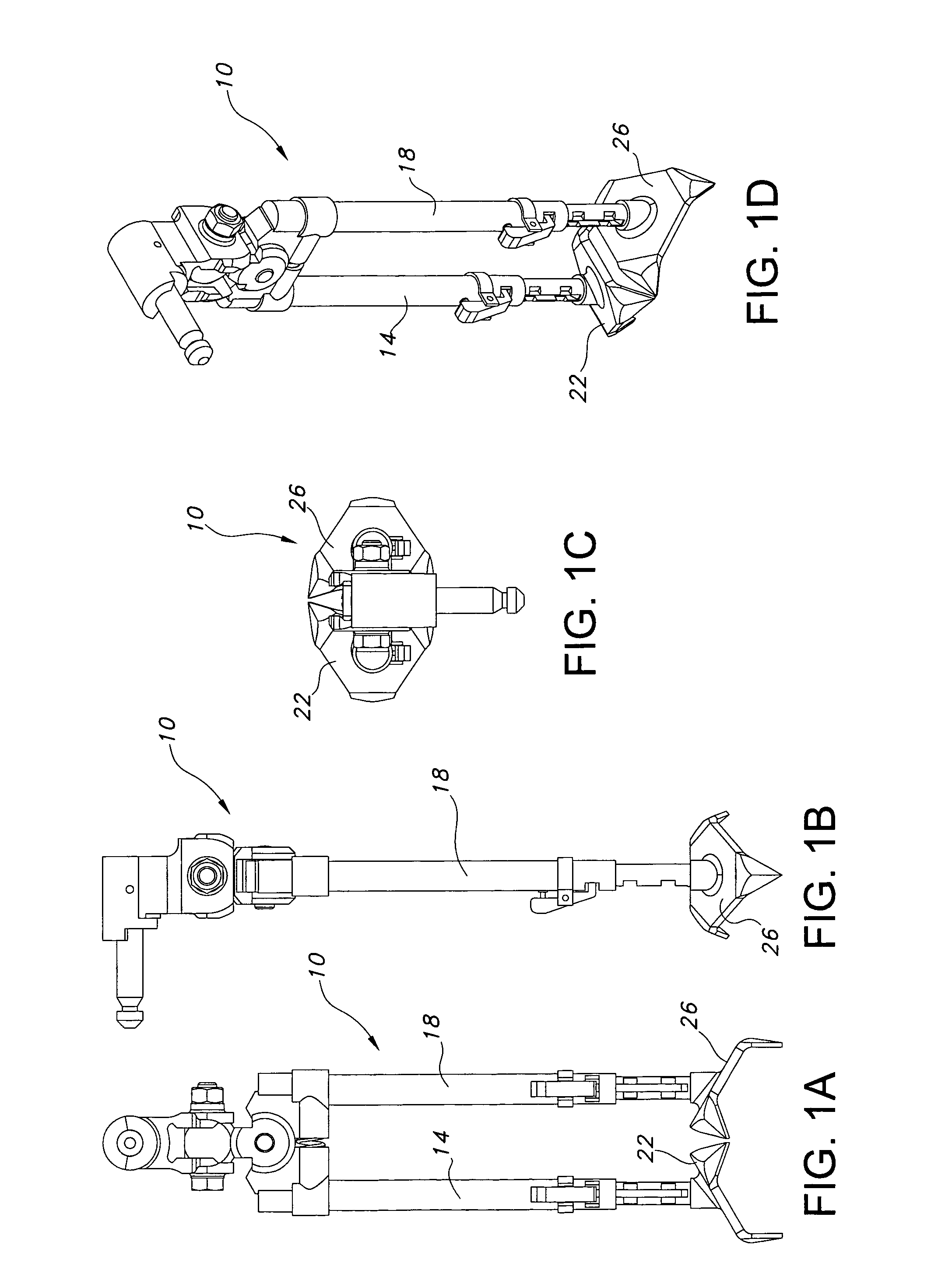
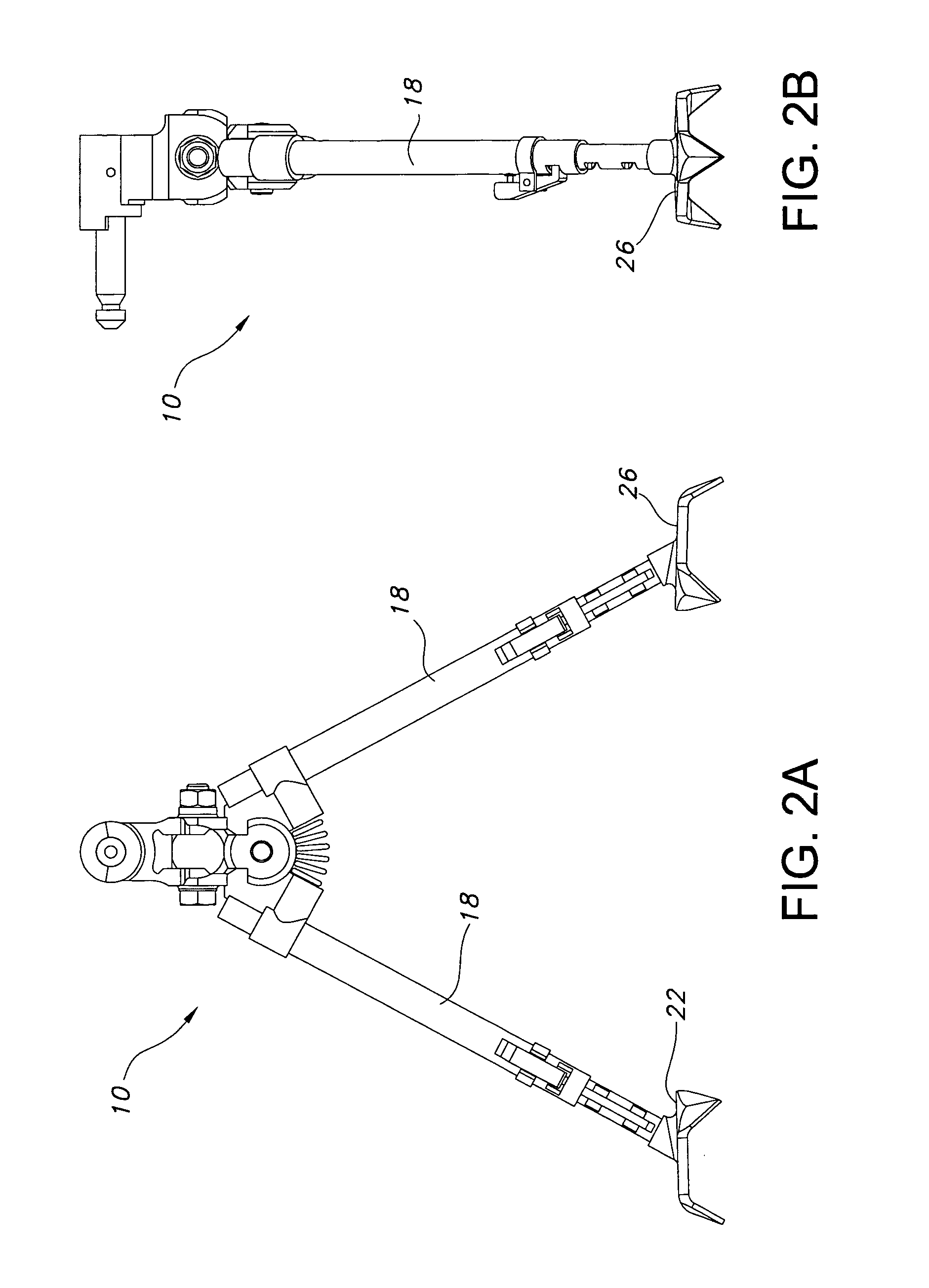
[0037] Referring now to FIGS. 1a-14h in which like numerals indicate like parts throughout the several views, the present invention comprises, in a first embodiment, a bipod assembly 10 adapted to support a firearm such as a rifle or another instrument when in the field.

[0038] Bipod support assembly 10 is configured to be releasably affixed to or mounted upon the forearm stock of a firearm such as a military rifle and includes first and second two-part, coaxially nested, tubular, spring-loaded telescopically extendable legs 14, 18 terminating distally in first and second substantially triangular, claw-like end effectors 22, 26.

[0039] Each end effecter (e.g., 26, best seen in FIGS. 5a-5d) includes a substantially planar central segment 30, having an upper surface 32 defining a polygon resembling a truncated triangle with the first, second and third radially arrayed corners or claws 40, 42, 44 projecting downwardly at an acute angle (e.g., downwardly at an angle of approximately 80 d...

second embodiment

[0047] In accordance with the present invention, a second embodiment, illustrated in FIGS. 6a-14h includes an alternative embodiment for the end effecters and claws as well as an adjustable clamping mechanism adapted to securely fasten the bipod assembly 110 to the forearm of a rifle or other weapon (e.g. such as an M-249 Squad Automatic Weapon “SAW”) as might be used, for example, by the military.

[0048] Clamping Bipod assembly 110 includes first and second extendable bipod legs 114,116 terminating distally in first and second claw-shaped end effecters 122, 126. Each of the end effecters includes a substantially planar central segment 130 having an upper surface 132 opposite a substantially planar lower surface 134. Each end effecter (for example, end effecter 126) is shaped as a triangle having drooping corners to define radially arrayed downwardly depending claw members as shown in the figures. A first claw 140 is spaced at an equal angle (120° apart) from second claw member 142 a...


PUM


Abstract

A bipod comprises first and second tubular, spring-loaded telescopically extendable legs terminating distally in substantially triangular, claw-like end effectors. Each end effecter includes a substantially planar central segment having an upper surface defining a polygon resembling a truncated triangle with the first, second and third corners projecting downwardly at an acute angle. The first second and third downwardly projecting corner segments define substantially planar, triangular claw members, and so form a cup-shaped three pointed claw ideally well suited to grasp but not sink into any terrain surface.

Description

RELATED PATENT APPLICATION AND PRIORITY CLAIM INFORMATION [0001] This application claims priority to and is owned by the applicant / owner of co-pending provisional application No. 60 / 643,108, filed Jan. 12, 2005, the entire disclosure of which is incorporated herein by reference. This application is also owned by the applicant / owner of U.S. Pat. No. 5,711,103 and U.S. Pat. No. 5,815,974, the entire disclosures of which are incorporated herein by reference. Additionally, this application is owned by the applicant / owner of provisional application No. 60 / 338,153, filed Nov. 13, 2001, the entire disclosure of which is also incorporated herein by reference.BACKGROUND OF THE INVENTION [0002] 1. Field of the Invention [0003] The present invention relates to an apparatus and method for supporting a firearm or other apparatus when in the field, and more particularly to a support device such as a bipod adapted to support the muzzle or stock of a firearm on snow, mud, soil, soft terrain, hard t...

Claims


Application Information

Patent Timeline
IPC IPC(8): F16M11/32
CPCF16M11/36F41A23/10F41A23/54F16M2200/08F16M11/26F16M2200/028F16M11/245
Inventor KENG, DAMATUSZCZAK, MACIEJ W.
Owner KENGS FIREARMS SPECIALTY
Why Eureka
Try Eureka