Distributed network monitoring system

a network monitoring and distributed network technology, applied in the field of distributed network monitoring system architecture and operation, can solve the problems of inability to monitor all the nodes or communication links associated with large enterprise networks or networks of networks, inability to monitor the entire network, and inability to meet the needs of information technology professionals

Inactive Publication Date: 2006-12-14
OPNET TECH LLC
View PDF3 Cites 84 Cited by
  • Summary
  • Abstract
  • Description
  • Claims
  • Application Information

AI Technical Summary

Benefits of technology

[0005] A distributed network monitoring system includes a central monitoring device configured to store global configuration information for all monitoring devices which make up the distributed monitoring system, and one or more remote monitoring devices communicatively coupled to the central monitoring device and configured to receive, in response to a request therefor, at least a portion of the configuration information from the central monitoring device. The remote monitoring devices and the central monitoring device may be communicatively coupled through respective secure communications paths (e.g., SSH communication tunnels) established on an as-needed basis by secure communication tunnel processes

Problems solved by technology

Today, information technology professionals often encounter a myriad of different problems and challenges during the operation of a computer network or network of networks.
For example, these individuals must often cope with network device failures and/or software application errors brought about by such things as configuration errors or ot

Method used


Image

  • Distributed network monitoring system
  • Distributed network monitoring system
  • Distributed network monitoring system

Examples


Embodiment Construction

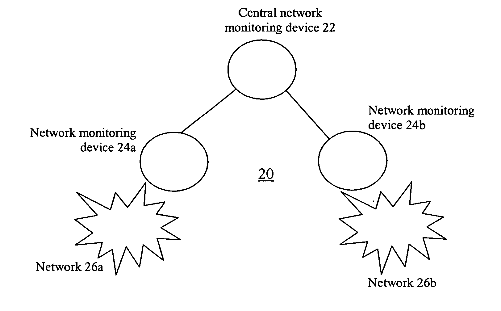
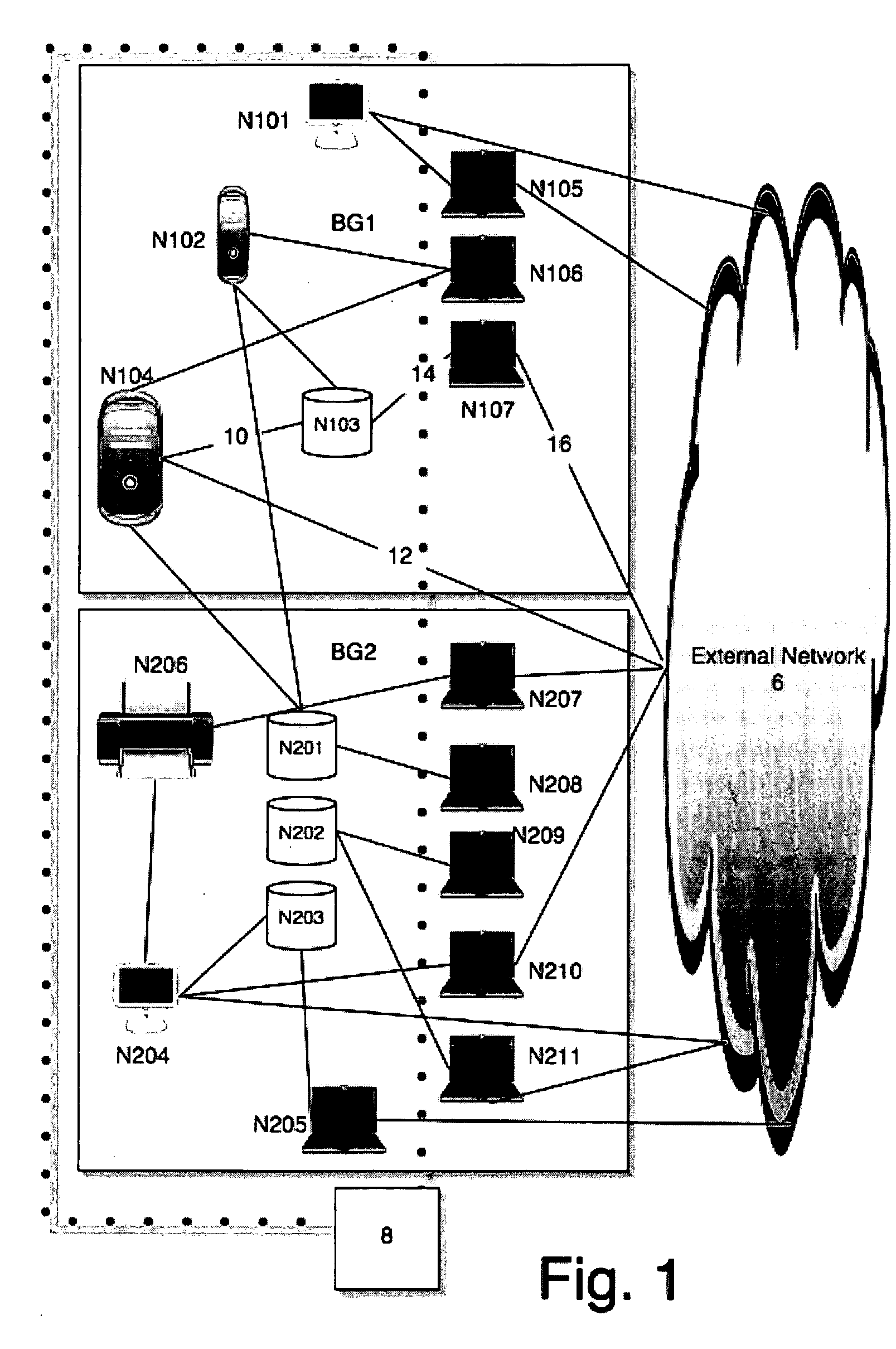
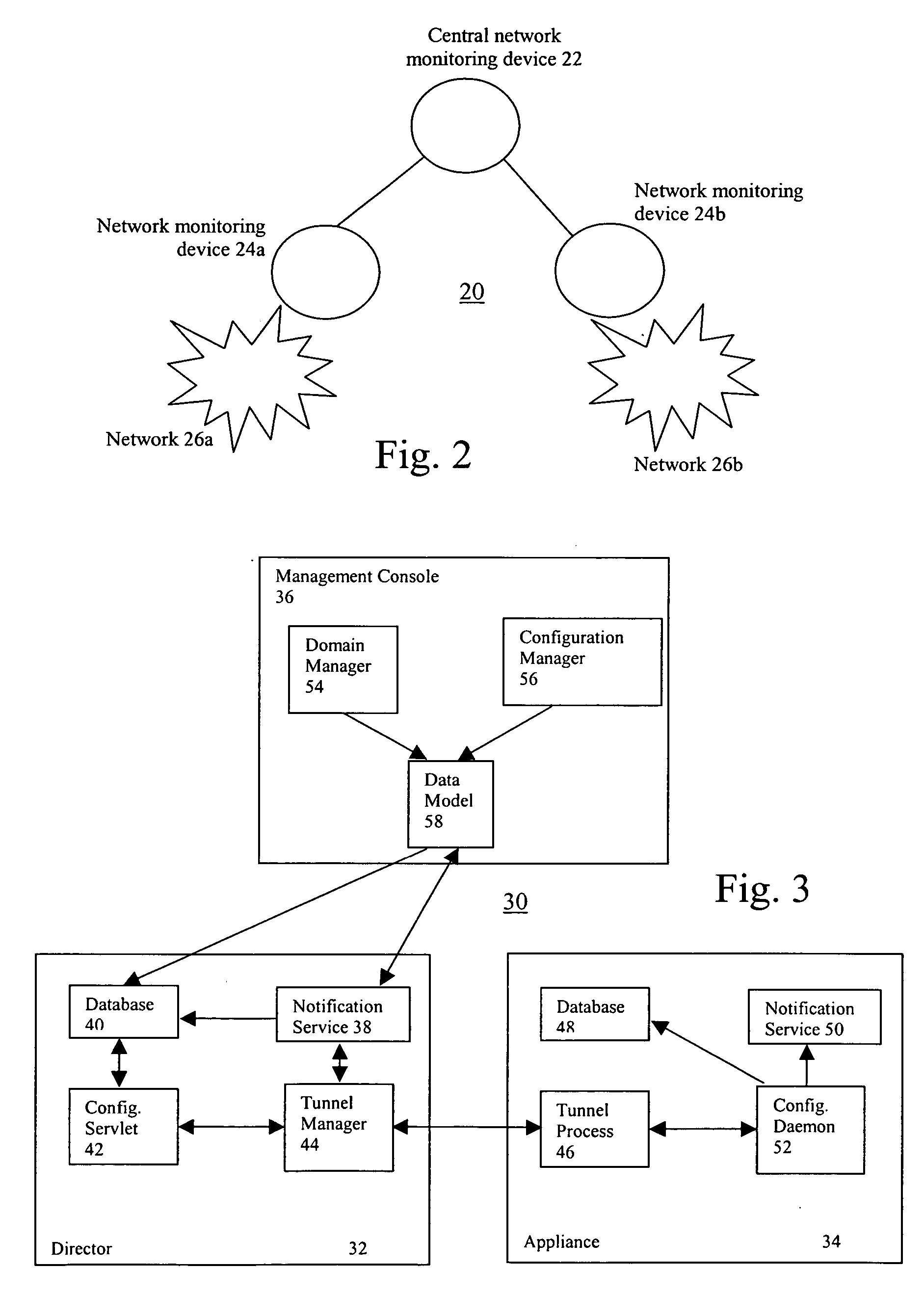
[0013] Described herein is a distributed network monitoring system adapted for monitoring one or more computer networks or networks of networks. Although discussed with respect to various illustrated embodiments, however, the present invention is not meant to be limited thereby. Instead, these illustrations are provided to highlight various features of the present invention. The invention itself should be measured only in terms of the claims following this description.

[0014] Various embodiments of the present invention may be implemented with the aid of computer-implemented processes or methods (a.k.a. programs or routines) that may be rendered in any computer language including, without limitation, C#, C / C++, Fortran, COBOL, PASCAL, assembly language, markup languages (e.g., HTML, SGML, XML, VOXML), and the like, as well as object-oriented environments such as the Common Object Request Broker Architecture (CORBA), Java™ and the like. In general, however, all of the aforementioned ...


PUM


Abstract

A distributed network monitoring system includes a central monitoring device configured to store global configuration information for all monitoring devices which make up the distributed system, and one or more remote monitoring devices configured to receive, in response to a request therefor, at least a portion of the configuration information from the central monitoring device. The remote monitoring devices and the central monitoring device may be communicatively coupled through respective secure communications paths (e.g., SSH communication tunnels) established on an as-needed basis by secure communication tunnel processes executing at the central monitoring device and remote monitoring devices. The central network monitoring device may further include a configuration servlet configured to provide requested portions of the configuration information to the one or more remote monitoring devices.

Description

FIELD OF THE INVENTION [0001] The present invention relates to the architecture and operation of a distributed network monitoring system configured for monitoring operations of one or more computer networks. BACKGROUND [0002] Today, information technology professionals often encounter a myriad of different problems and challenges during the operation of a computer network or network of networks. For example, these individuals must often cope with network device failures and / or software application errors brought about by such things as configuration errors or other causes. In order to permit network operators and managers to track down the sources of such problems, network monitoring devices capable of recording and logging vast amounts of information concerning network communications have been developed. [0003] Conventional network monitoring devices, however, suffer from scalability problems. For example, because of finite storage space associated with such devices, conventional n...

Claims


Application Information

Patent Timeline
IPC IPC(8): H04J3/12
CPCH04L41/0853H04L63/0428H04L43/12
Inventor GUARINI, STEPHENPAVEL, TOMAS J.CRANE, MARKSEILNACHT, ERIKKANG, ROMAIN
Owner OPNET TECH LLC
Why Eureka
Try Eureka