Method and apparatus of multi-energy imaging

Inactive Publication Date: 2006-12-14
GENERAL ELECTRIC CO
View PDF20 Cites 5 Cited by
  • Summary
  • Abstract
  • Description
  • Claims
  • Application Information

AI Technical Summary

Benefits of technology

[0012] In accordance with yet a further aspect of the present invention, a computer readable storage medium has a computer program stored thereon. The computer program represents a set of instructions that when executed by a computer causes the computer to energize the high frequency electromagnetic energy source to a first voltage to cause the high frequency electromagnetic energy source to project a first beam of electromagnetic energy toward the subject to be scanned. The computer is further caused to position a first filter between the high frequency electromagnetic energy source and the subject during energization of the high frequency electromagnetic energy source to the first voltage. The set of instructions further causes the computer to energize the high frequency electromagnetic energy source to a second voltage to cause the high frequency electromagnetic energy source to project a second beam of electromagnetic energy toward the subject and position a second filter between the electromagnetic energy source and the subject during energization of the high frequency electromagnetic energy source to the second voltage.

Problems solved by technology

Simply scanning at two kVp potentials in an interleaved manner is not desirable as filtration of the dual energy levels remains a concern.
For example, dual energy CT scanning with fixed filtration results in a dramatic decrease in signal strength when comparing the 80 kVp spectrum to the 140 kVp spectrum.

Method used


Image

  • Method and apparatus of multi-energy imaging
  • Method and apparatus of multi-energy imaging
  • Method and apparatus of multi-energy imaging

Examples


Embodiment Construction

[0026] The operating environment of the present invention is described with respect to a four-slice computed tomography (CT) system. However, it will be appreciated by those skilled in the art that the present invention is equally applicable for use with single-slice or other multi-slice configurations. Moreover, the present invention will be described with respect to the detection and conversion of x-rays. However, one skilled in the art will further appreciate, that the present invention is equally applicable for the detection and conversion of other high frequency electromagnetic energy. The present invention will be described with respect to a “third generation” CT scanner, but is equivalently applicable with other CT systems.

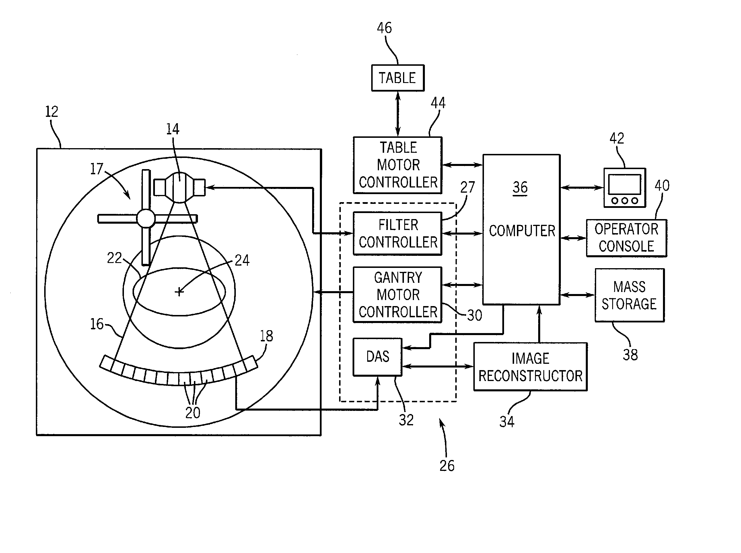
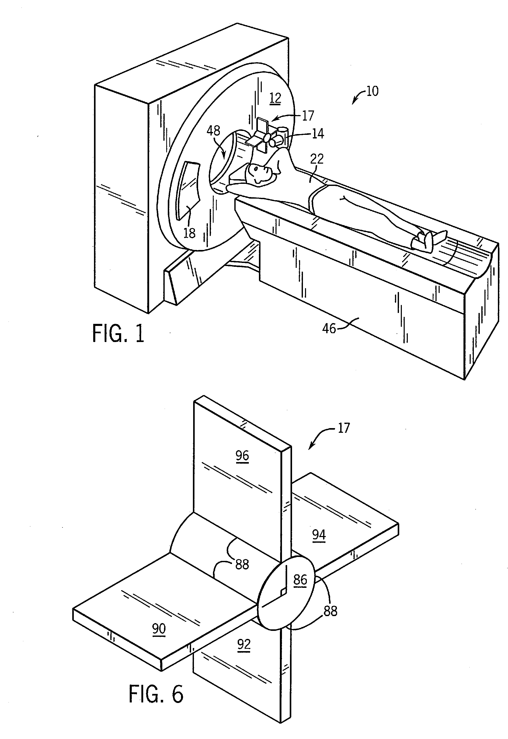
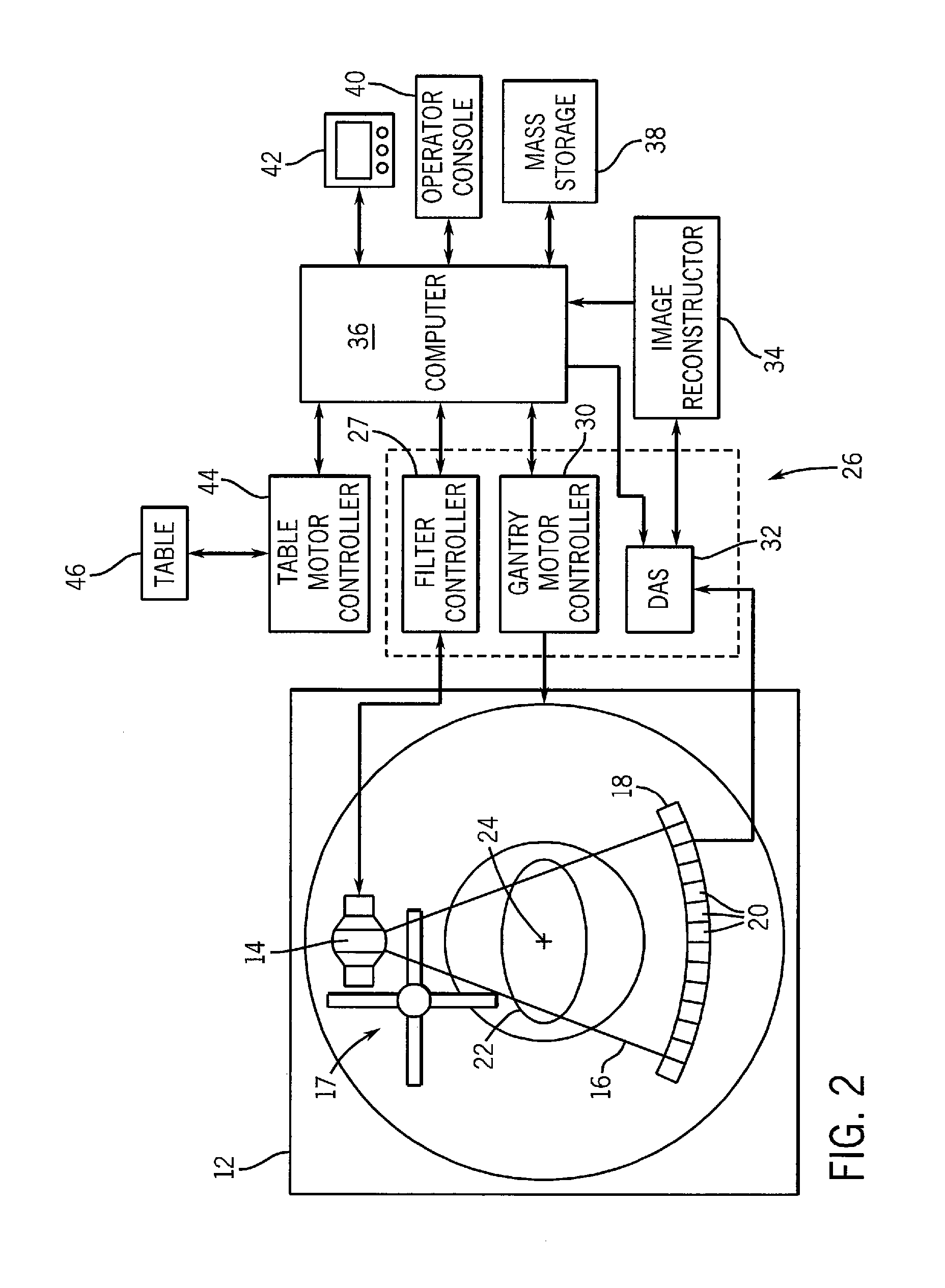
[0027] Referring to FIGS. 1 and 2, a computed tomography (CT) imaging system 10 is shown as including a gantry 12 representative of a “third generation” CT scanner. Gantry 12 has an x-ray source 14 that projects a beam of x-rays 16 toward a filtering appar...


PUM


Abstract

The present invention is directed to a method and apparatus of multi-energy data acquisition. An imaging system is also provided and includes a number of HF electromagnetic energy filters. The filters include at least a first and a second filter wherein the first filter is positioned in a path of HF electromagnetic energy when an HF electromagnetic energy source is energized to a first voltage and the second filter is positioned in the path of HF electromagnetic energy when the HF electromagnetic energy source is energized to a second voltage.

Description

CROSS REFERENCE TO RELATED APPLICATIONS [0001] The present application is a continuation of and claims priority of U.S. Ser. No. 10 / 063,366 filed Apr. 16, 2002, the disclosure of which is incorporated herein by reference.BACKGROUND OF THE INVENTION [0002] The present invention relates generally to diagnostic imaging and, more particularly, to a method and apparatus of acquiring imaging data at more than one energy range using multi-energy high speed switching filters. [0003] Typically, in computed tomography (CT) imaging systems, an x-ray source emits a fan-shaped beam toward a subject or object, such as a patient or a piece of luggage. Hereinafter, the terms “subject” and “object” shall include anything capable of being imaged. The beam, after being attenuated by the subject, impinges upon an array of radiation detectors. The intensity of the attenuated beam radiation received at the detector array is typically dependent upon the attenuation of the x-ray beam by the subject. Each d...

Claims


Application Information

Patent Timeline
IPC IPC(8): H05G1/60A61B6/00G01N23/00G21K1/12G01N23/04A61B6/03G21K1/10G21K3/00
CPCA61B6/032A61B6/4035G21K1/10A61B6/482A61B6/405
Inventor TOTH, THOMAS L.
Owner GENERAL ELECTRIC CO
Why Eureka
Try Eureka