Plastic tolerance compensating assembly

a technology of tolerance compensating assembly and plastic, which is applied in the direction of sheet joining, fastening means, washing machines, etc., can solve the problems of diminishing clamping between the two structural members and relatively expensive known tolerance compensating assemblies, and achieve the effect of economic manufactur

Inactive Publication Date: 2006-12-14
BOLLHOFF VERBINDUNGSTECHNIK GMBH
View PDF9 Cites 45 Cited by
  • Summary
  • Abstract
  • Description
  • Claims
  • Application Information

AI Technical Summary

Benefits of technology

[0004] It is the object of the present invention to provide a tolerance compensating assembly for automatically compensating tolerances in the spacing between two pre-mounted structural members which are to be clamped together which can be manufactured economically and of a configuration suitable for manufacturing from plastic.

Problems solved by technology

These known tolerance compensating assemblies are relatively expensive and those which make use of thermoplastic synthetics have the disadvantage of the clamping between the two structural members diminishing due to the relaxation of the plastic.

Method used


Image

  • Plastic tolerance compensating assembly
  • Plastic tolerance compensating assembly
  • Plastic tolerance compensating assembly

Examples


Embodiment Construction

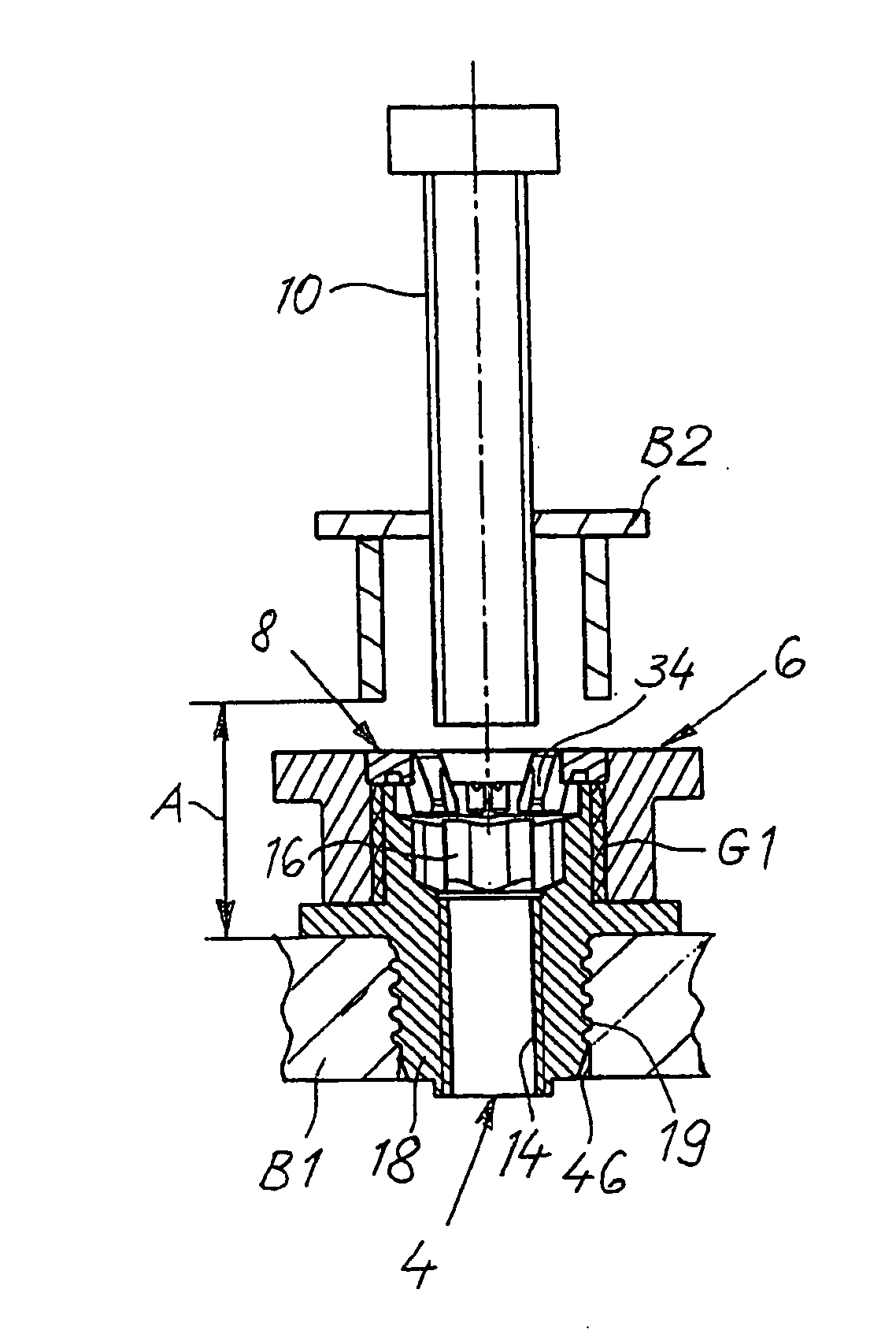
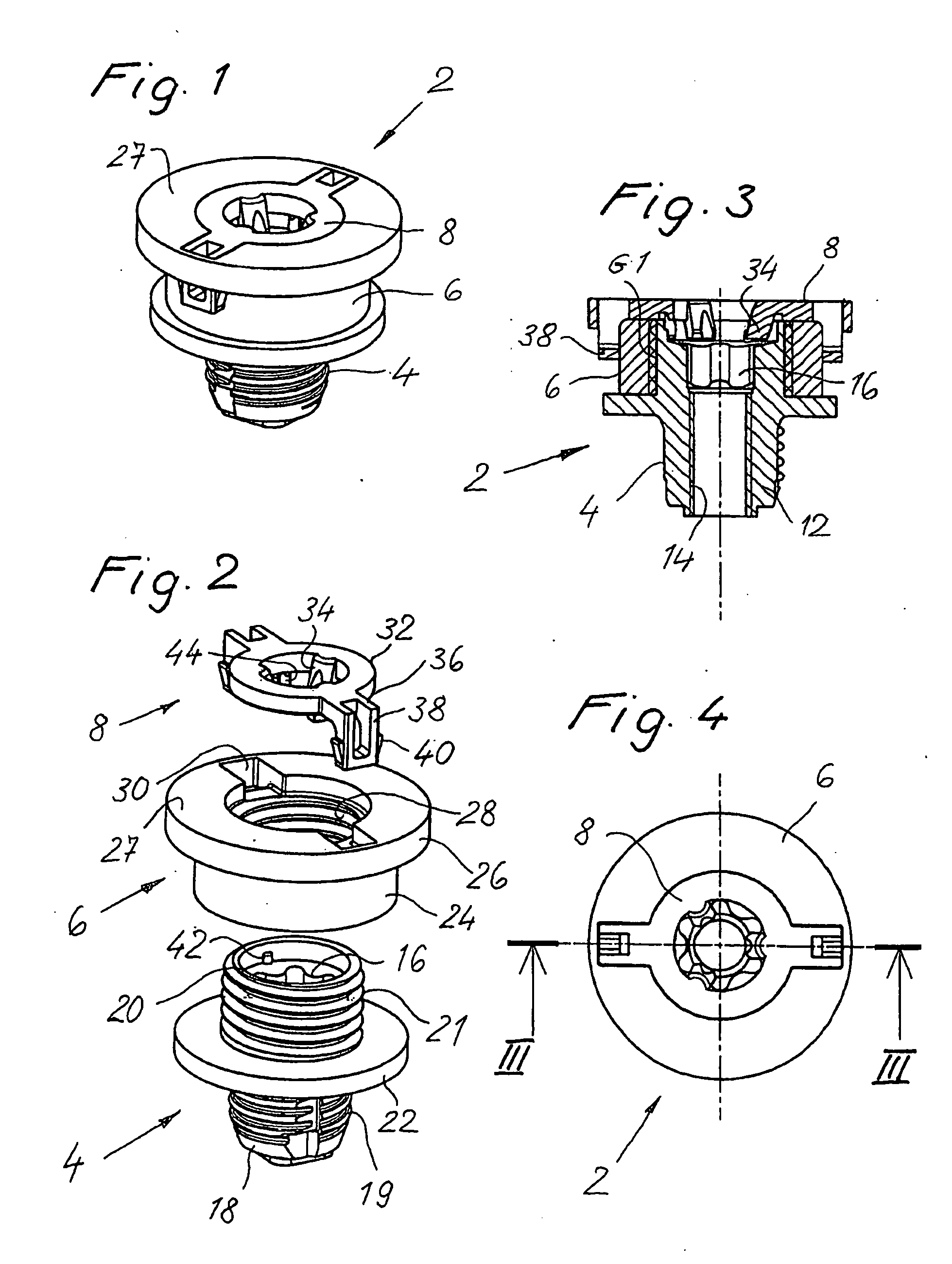
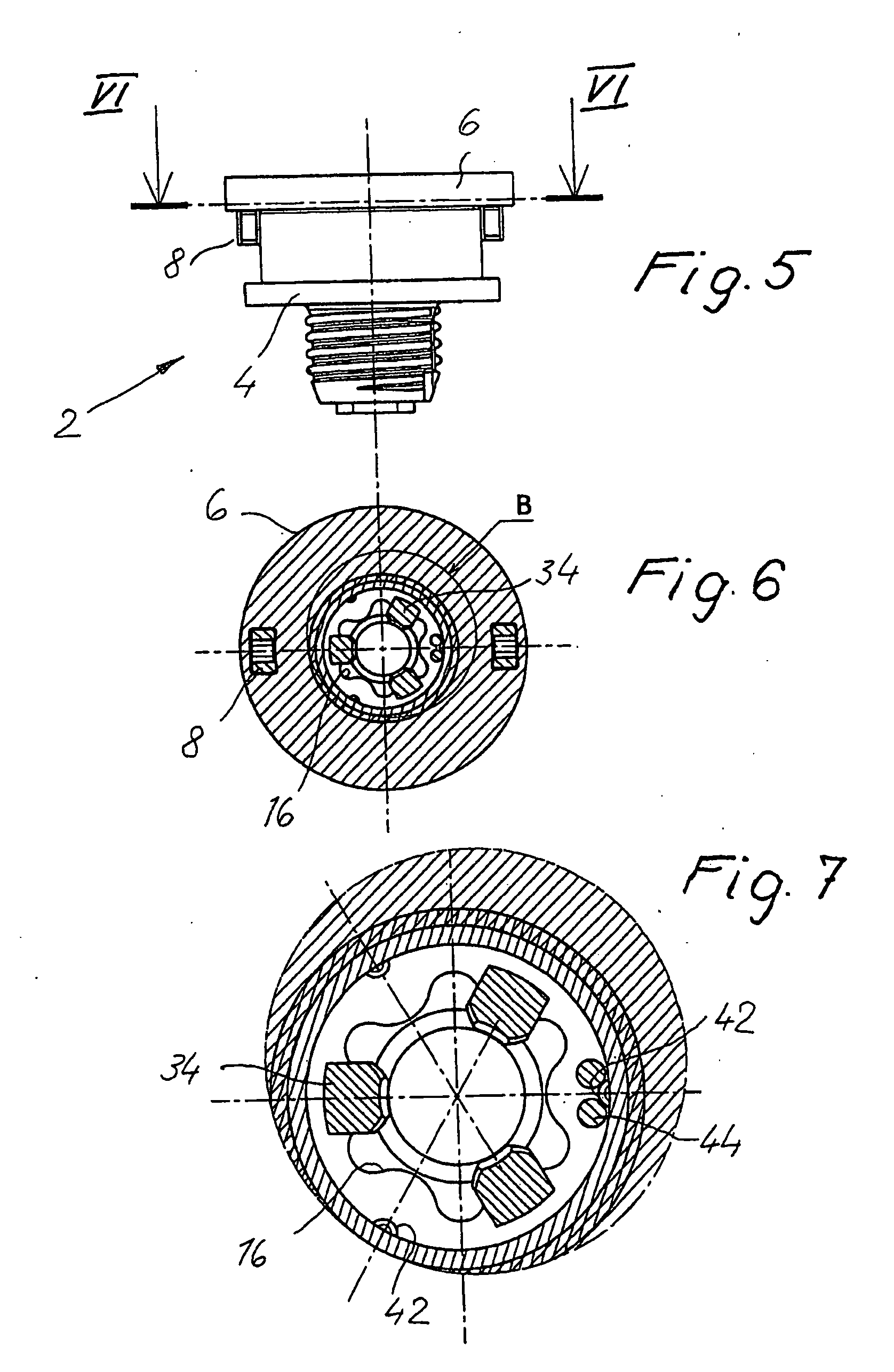
[0023] FIGS. 1 to 7 show a structural unit 2 for a tolerance compensating assembly as depicted in FIGS. 8 to 10. The structural unit 2, which forms the tolerance compensating assembly together with a conventional mounting bolt 10 (FIGS. 8, 9), consists of a base element 4, an adjustment sleeve 6 and a driver 8, as can especially be seen in FIG. 2.

[0024] The base element 4 (see FIGS. 2 and 3 in particular) consist of a sleeve-shaped body 12 having a throughbore disposed with an internal thread 14 and, adjacent thereto, a drive feature 16 for attachment of a tool (not shown). The drive feature 16 is configured as an internal six-lobe recess head in the exemplary embodiment as shown but may, however, also be of a different configuration.

[0025] The sleeve-shaped body 12 consists of a mounting portion 18 and an adjustment portion 20, separated by an annular flange 22. The mounting portion 18 has a thread 19 at its outer periphery in the exemplary embodiment shown and serves to fix the ...


PUM


Abstract

A tolerance compensating assembly of automatically compensating tolerances in the spacing between two structural members comprises a mounting bolt 10, a base element 4, an adjustment sleeve 6 and a driver 8. The base element 4 and the adjustment sleeve 6 form a first thread pairing G1 of a predetermined spiral direction for adjusting the adjustment sleeve 6 relative to the base element 4. The base element 4 and the mounting bolt 10 form a second thread pairing G2 in the opposite spiral direction for clamping the two structural members B1, B2. The driver 8 is a separate structural member and disengageably connected to the adjustment sleeve 6 and has a plurality of flexibly resilient clamping portions 34 spaced along its periphery, which provide for frictional contact with the thread of the mounting bolt 10 above a predetermined torsional force.

Description

BACKGROUND OF THE INVENTION [0001] The present invention relates to a tolerance compensating assembly for automatically compensating tolerances in the spacing between two pre-mounted structural members or structural members to be mounted which are to be clamped together. [0002] A great number of such tolerance compensating assemblies are known, see for example EP 0 176 663 B1, DE 42 24 575 C2, DE 101 51 383 A1, DE-GM 201 190012 and DE-GM 203 14 003. They serve in compensating the tolerance between pre-mounted structural members which ensues in manufacturing and / or mounting. To this end, these tolerance compensating assemblies normally comprise an adjustment sleeve having a so-called drive portion which can enter into frictional contact connection with a mounting bolt. Upon rotating the mounting bolt, the adjustment sleeve is therefore also rotated until it is fixedly supported against one of the structural members to be clamped, whereupon given further rotation of the mounting bolt ...

Claims


Application Information

Patent Timeline
Patent Type & Authority Applications(United States)
IPC IPC(8): F16B43/02F16B5/02
CPCF16B5/025F16B5/0233
Inventor SEIDL, JORGKLEIN, UWEFIGGE, HANS-ULRICHHESSE, WOLFGANG
Owner BOLLHOFF VERBINDUNGSTECHNIK GMBH
Why Eureka
Try Eureka