System and method for upper extremity joint arthroplasty

a technology for upper extremity joints and implants, applied in knee joints, prostheses, medical science, etc., can solve problems such as pain, swelling, and significant impact on patient fine motor skills, and achieve the effects of improving patient comfort, improving patient comfort, and improving patient comfor

Inactive Publication Date: 2006-12-14
ABS
View PDF75 Cites 80 Cited by
  • Summary
  • Abstract
  • Description
  • Claims
  • Application Information

AI Technical Summary

Problems solved by technology

Loss of radial head rotation or significant pain from motion will significantly impact fine motor skills of a patient.
Similar conditions can cause damage to the distal ulna.
Unfortunately, the significant hardness and modulus mismatch between the implant and the bone that it must articulate with leads to milling and erosions in the adjacent bone with resultant pain, swelling and reduced function.
Further, it can ultimately lead to failure of the implant.

Method used


Image

  • System and method for upper extremity joint arthroplasty
  • System and method for upper extremity joint arthroplasty
  • System and method for upper extremity joint arthroplasty

Examples


Embodiment Construction

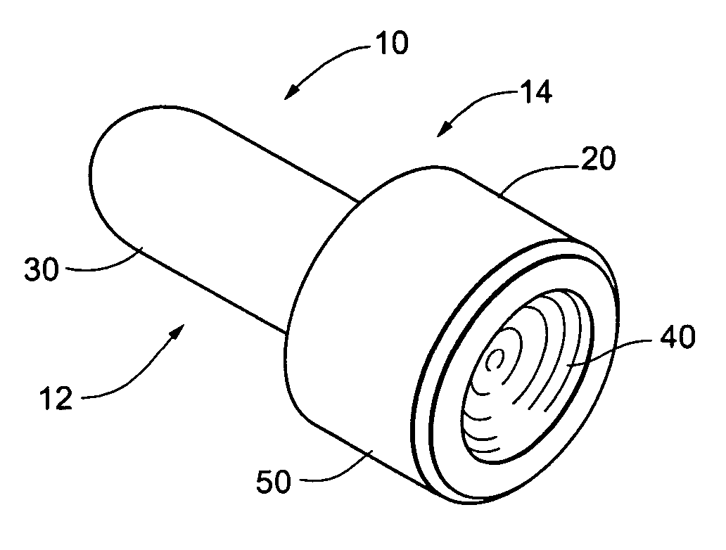
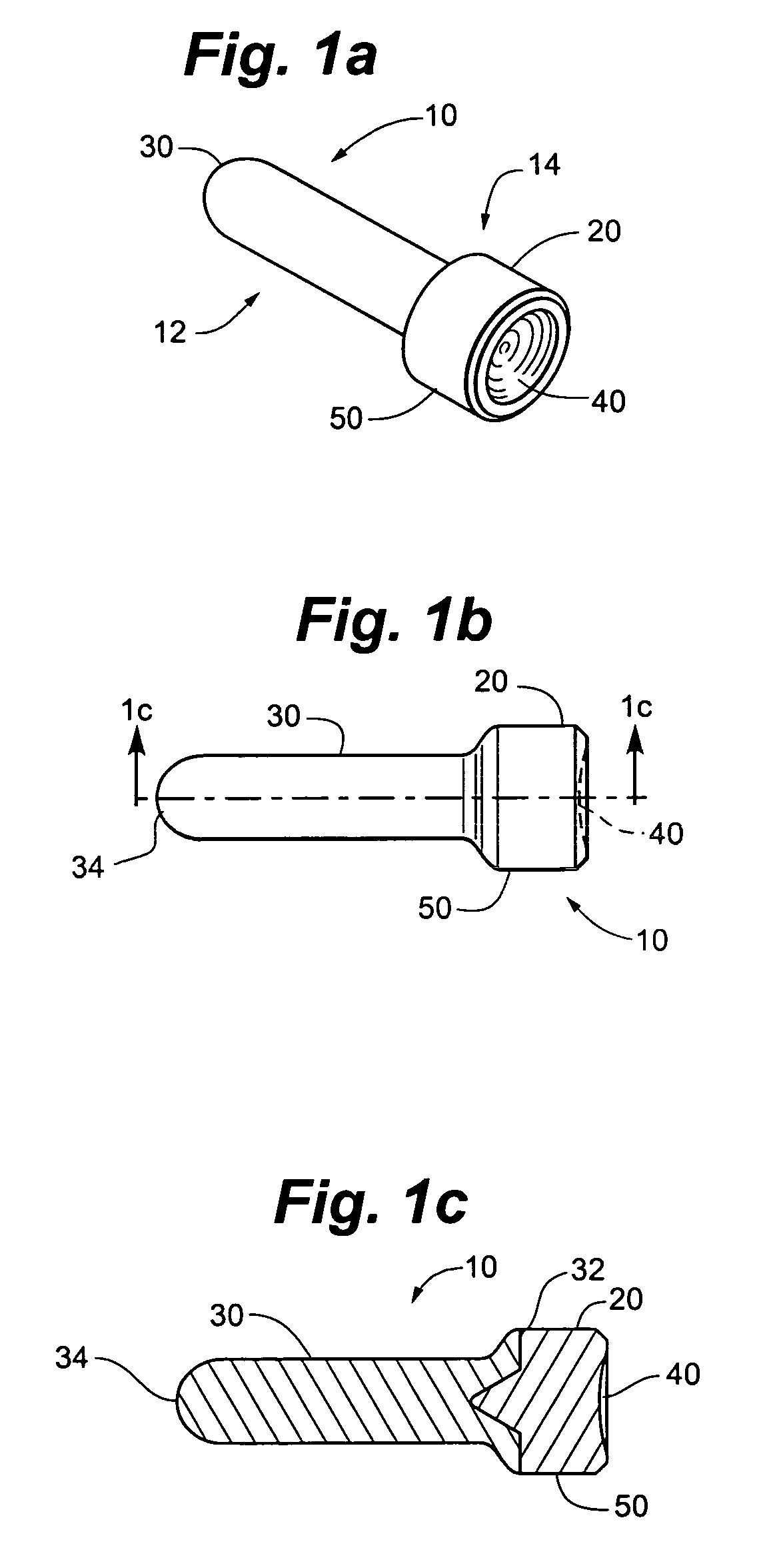
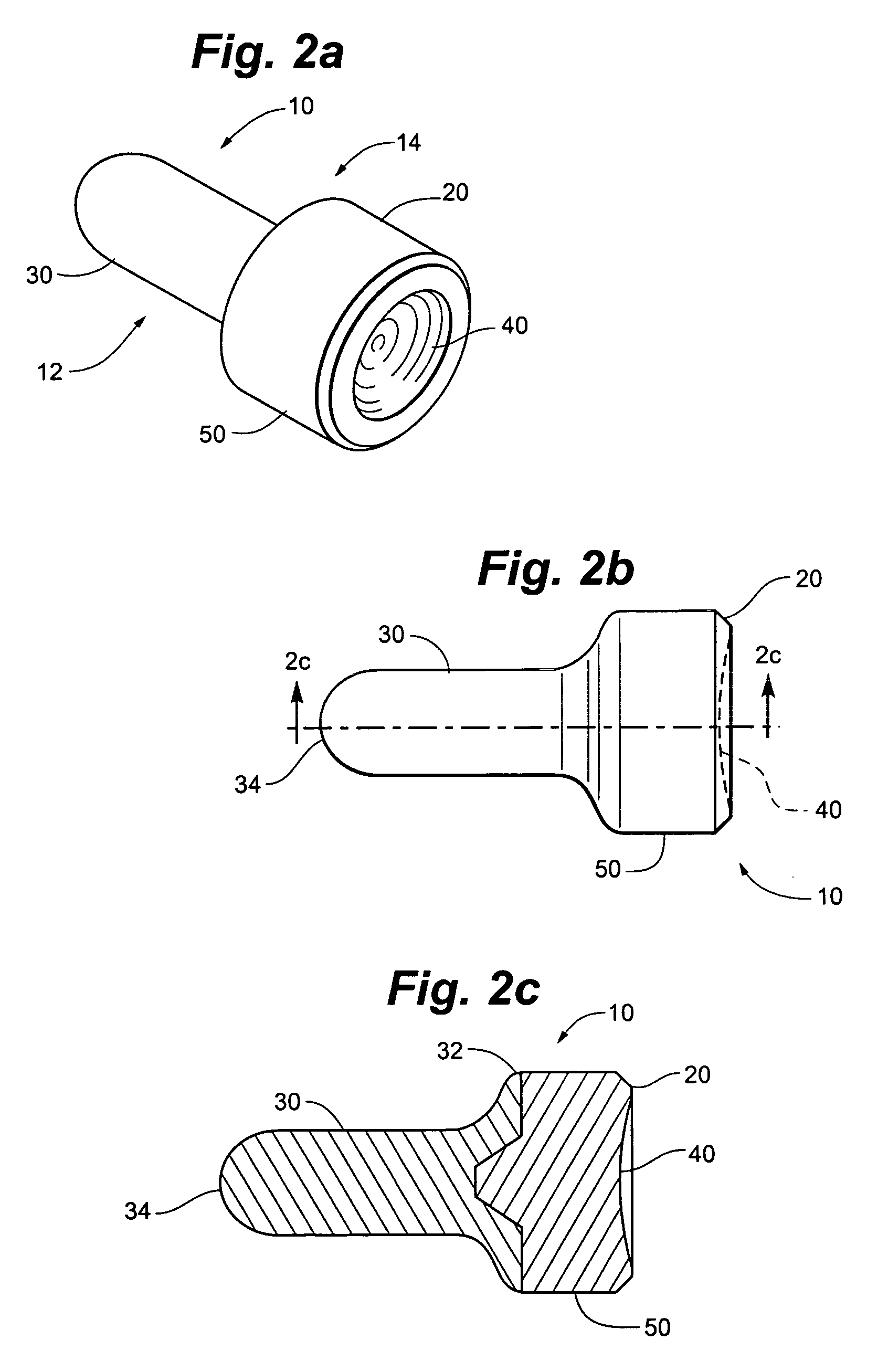
[0020] A preferred embodiment of the method and implant of this invention will be further described with reference to the Drawing, in which FIGS. 1(a)-2(c) show various views of an implant 10 in accordance with embodiments of the invention. In some embodiments, as in FIGS. 1(a) and 2(a), the invention provides an implant for an upper extremity joint arthroplasty, the implant comprising a first polymeric portion 12 adapted to be retained within a bone of the upper extremity and a second polymeric portion 14 having an articulating surface adapted to articulate against an opposing bone. As shown in FIG. 3, in some embodiments the bone of the upper extremity is a radius 15 and the opposing bone is selected from the group of an ulna 16, a humorous 17, and combinations thereof (i.e., the elbow). In other embodiments, the bone of the upper extremity is an ulna 16 and the opposing bone is selected from the group of a radius 15, a carpal 18, and combinations thereof (i.e., the wrist).

[0021]...


PUM

PropertyMeasurementUnit
compressive modulusaaaaaaaaaa
lengthaaaaaaaaaa

Abstract

The invention can provide an implant for an upper extremity joint arthroplasty having a first polymeric portion adapted to be retained within a bone of the upper extremity and a second polymeric portion having an articulating surface adapted to articulate against an opposing bone. The invention can also provide methods of making and using such an implant.

Description

RELATED APPLICATIONS [0001] This application claims priority to U.S. Provisional Patent Application Ser. No. 60 / 637,136, titled Radial Head and Distal Ulna Prosthesis, filed Dec. 17, 2004, the contents of which are hereby incorporated by reference.TECHNICAL FIELD [0002] In one aspect, this invention relates to materials for implantation and use within the body. In another aspect, this invention further relates to the field of orthopedic implants and prosthesis, and more particularly, for implantable materials for use in joint arthroplasty. BACKGROUND OF THE INVENTION [0003] Radioulnar joints are synovial joints of the upper extremity. The proximal joint lies between the head of radius and the radial notch of the ulna, while the distal joint is separated from the wrist by an articular disc that extends from base of ulnar styloid process to the radius. The radial head articulates at the elbow with the olecranon process of the ulna and rotates in the intercondylar fossa between the med...

Claims


Application Information

Patent Timeline
Patent Type & Authority Applications(United States)
IPC IPC(8): A61F2/38
CPCA61F2/3804A61F2/4261A61F2/4603A61F2002/30616A61F2002/3827A61F2002/3831A61F2002/4264A61L27/18A61F2002/4266A61F2310/00011A61F2310/00179C08L75/04
Inventor FELT, JEFFREY C.RYDELL, MARK A.PURNELL, MICHAEL B.
Owner ABS
Why Eureka
Try Eureka