Rack-mounted bracket assembly

a bracket assembly and rack technology, applied in the direction of show hangers, variable dimension cabinets, cabinets, etc., can solve the problems of increasing hardware costs and increasing the time needed to install brackets

Inactive Publication Date: 2006-12-21
HEWLETT PACKARD DEV CO LP
View PDF26 Cites 43 Cited by
  • Summary
  • Abstract
  • Description
  • Claims
  • Application Information

AI Technical Summary

Benefits of technology

[0003] The problems noted above are solved in large part by a rack-mounted bracket assembly comprises a main member having a first end, a second end, and a shelf therebetween. A set of long tabs is disposed o

Problems solved by technology

Because the number of brackets increases, the hardware costs inc

Method used


Image

  • Rack-mounted bracket assembly
  • Rack-mounted bracket assembly
  • Rack-mounted bracket assembly

Examples


Embodiment Construction

[0014] The following discussion is directed to various embodiments of the invention. Although one or more of these embodiments may be preferred, the embodiments disclosed should not be interpreted, or otherwise used, as limiting the scope of the disclosure, including the claims. In addition, one skilled in the art will understand that the following description has broad application, and the discussion of any embodiment is meant only to be exemplary of that embodiment, and not intended to intimate that the scope of the disclosure, including the claims, is limited to that embodiment.

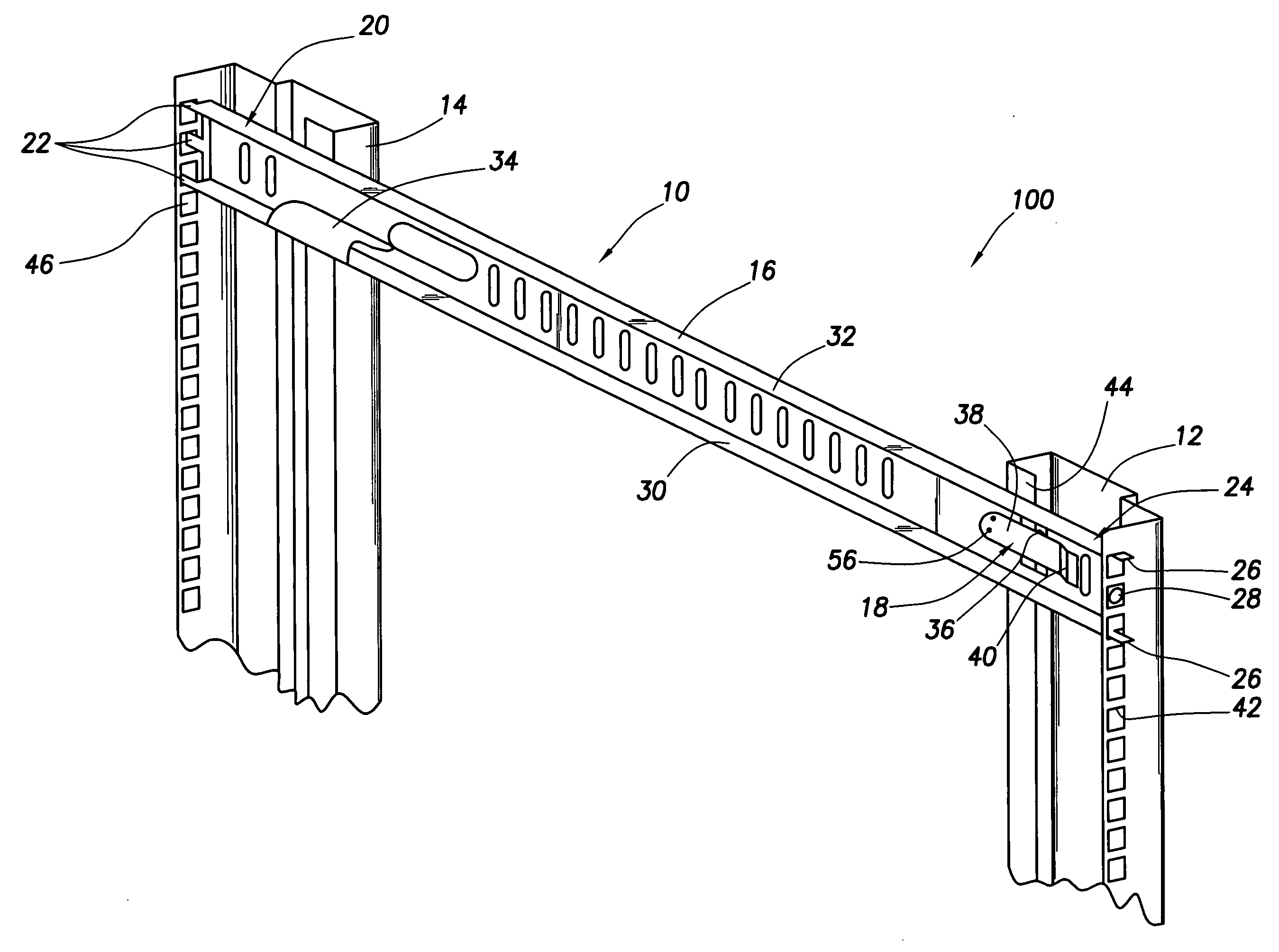
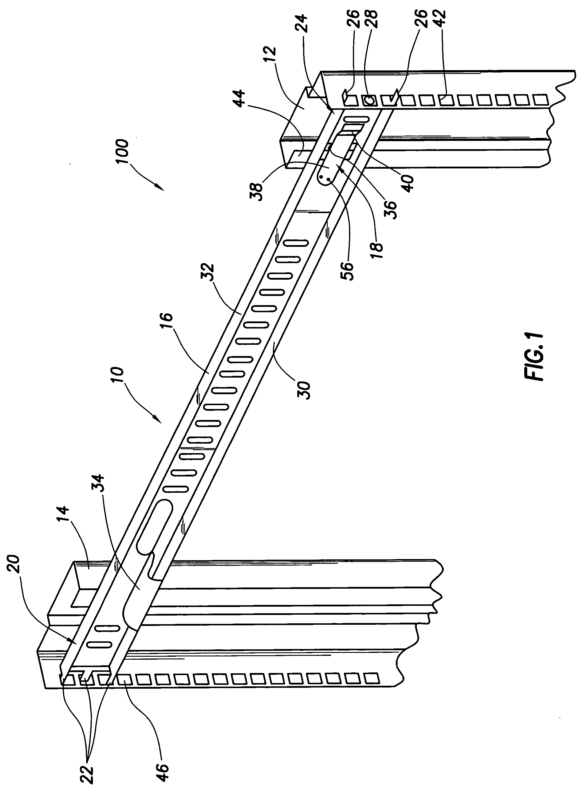
[0015] The figures presented herein illustrate a right-hand rack assembly. It is understood that a complimentary left-hand rack assembly would possess the same features as the right-hand assembly. Similarly, front and rear as used herein are merely descriptive terms and are not intended to be limiting recitations of the absolute position of any component.

[0016] Referring now to FIG. 1 a rack assembly 100...


PUM


Abstract

A rack-mounted bracket assembly comprises a main member having a first end, a second end, and a shelf therebetween. A set of long tabs is disposed on the first end of the main member. A set of short tabs is disposed on the second end of the main member. A retention latch is connected to the main member and limits the movement of the bracket within a rack.

Description

BACKGROUND [0001] For large-scale computing applications that require numerous servers, an industry standard EIA (Electronics Industries Alliance), or other type, rack is often used to contain servers in a stacked arrangement that uses the available space more efficiently. Such electronics racks are relatively simple structures that closely resemble open-frame bookcases. Computer server / component racks are typically constructed with perforated, hinged front-doors, rigid sides and a removable rear panel. Industry standard 19″ EIA electronics racks are designed typically to house a column of electronics packages that are 17¾″ in width with varying depths. The height of an electronics package can vary but is normally an integer multiple of an EIA unit called simply the “U.” An EIA U is 1.75 inches. Electronic equipment generally has a height in multiples of “Us” e.g., 1 U (1.75″), 2 U (3.50″), 3 U (5.25″), etc. [0002] Typically, electronic components may be secured within the rack usin...

Claims


Application Information

Patent Timeline
IPC IPC(8): A47F7/00
CPCA47B45/00H05K7/183A47B96/1441A47B57/48
Inventor MOORE, DAVID C.LEWIS, JEFFREY M.ROLLA, MICHAEL P.
Owner HEWLETT PACKARD DEV CO LP
Why Eureka
Try Eureka