
Wall plate masking device and method

a masking device and wall plate technology, applied in the direction of electrical appliances, etc., can solve the problems of time-consuming and inconvenience, and achieve the effect of reducing the time required for preparation and less tim

Inactive Publication Date: 2006-12-21
MERITAGE DESIGN A CALIFORNIA CORP
View PDF22 Cites 6 Cited by
  • Summary
  • Abstract
  • Description
  • Claims
  • Application Information

AI Technical Summary

Benefits of technology

[0007] The adhesive is of the type known in the adhesive field as a re-positionable adhesive, which is identical or similar to the adhesive used on Post-It® notes. Such adhesives are pressure sensitive, liquid glues which form a temporary bond to a surface and which can be easily pulled off without leaving any residue on the surface when no longer required.
[0008] The cover device may be of thermo-formed plastic material such as PVC which is thin enough to have some resilience. The dimensions of the peripheral rim may be slightly less than those of the rim of the wall plate it is designed to cover, so that the cover device must be forced over the wall plate and the rim will spread slightly over the rim of the wall plate, ensuring good adherence between the rim of the cover device and the rim of the wall plate. The device is very quick and easy to apply, and can be simply pushed or pressed onto the wall plate until the lower edge of the rim contacts the wall at the junction between the wall and rim of the wall plate. This will reduce the chance of any paint flowing under the edge of the cover device and onto any part of the wall plate.
[0016] The wall plate cover device and method of this invention will significantly reduce the time required to prepare the walls of a room for decorating. Rather than having to remove each wall plate and then cover the resultant exposed electrical fixture with masking tape or the like, the decorator simply presses a suitable cover device over every wall plate. Once decorating is complete, the cover devices are simply pulled off and discarded. This also will take much less time than removing masking tape and re-attaching the cover plates. Masking tape also has the disadvantage that it may mar the adjacent painted surface when it is pulled up. The device of this invention is not adhered to the surface, but only to the rim of the wall plate, and there will be no tendency to pull up any paint when it is pulled off.

Problems solved by technology

This is both time consuming and inconvenient.

Method used


Image

  • Wall plate masking device and method
  • Wall plate masking device and method
  • Wall plate masking device and method

Examples


Embodiment Construction

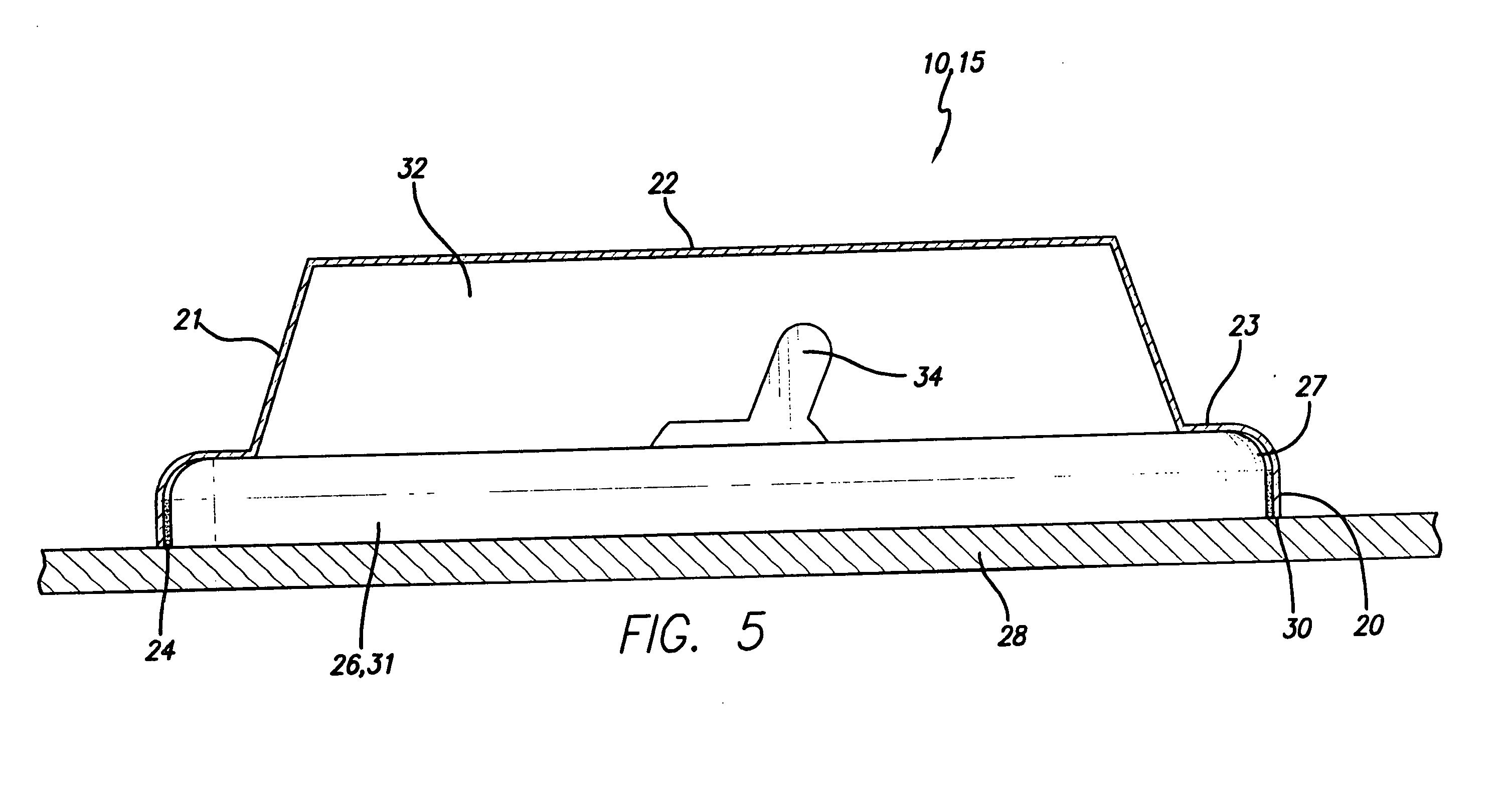
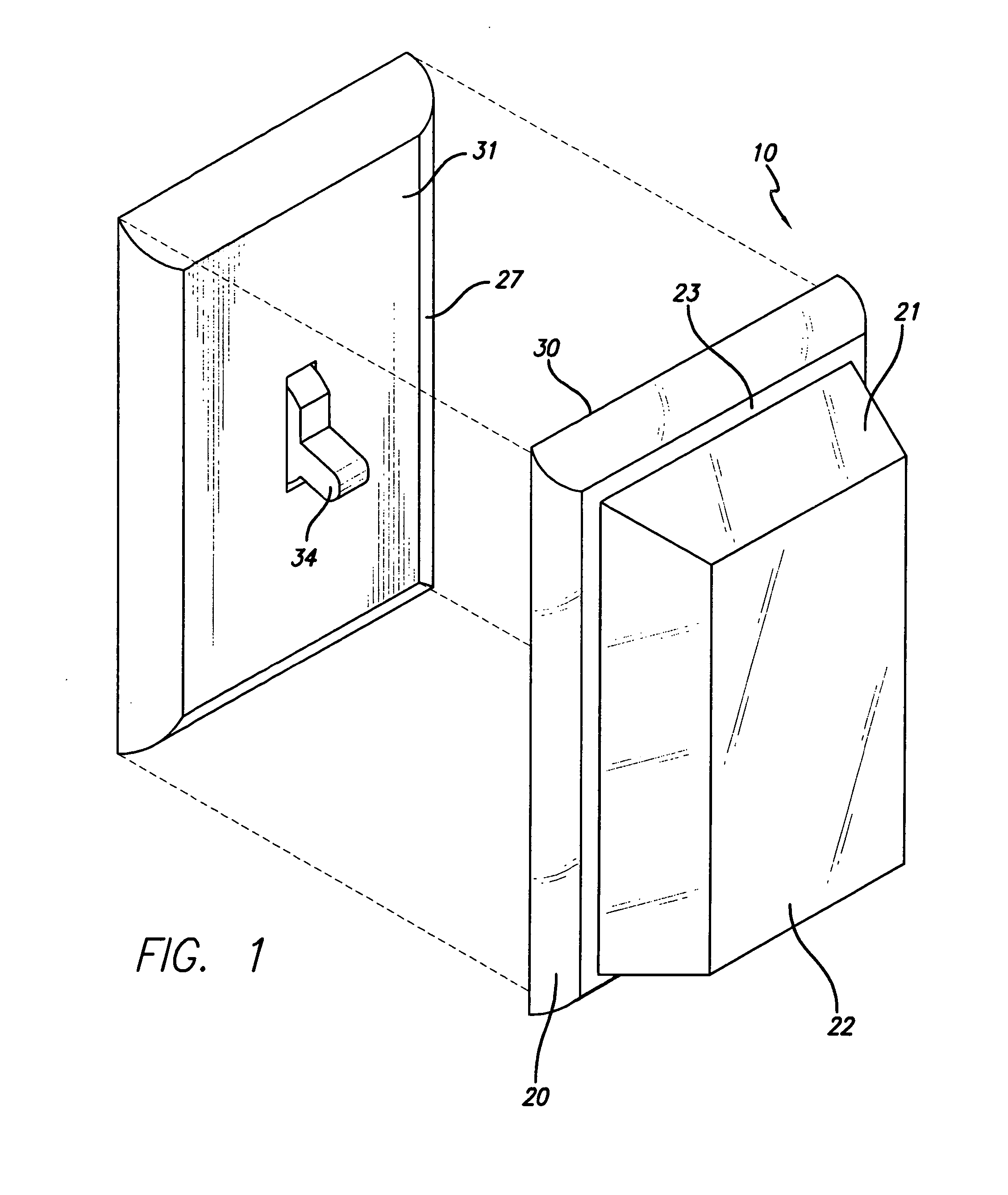
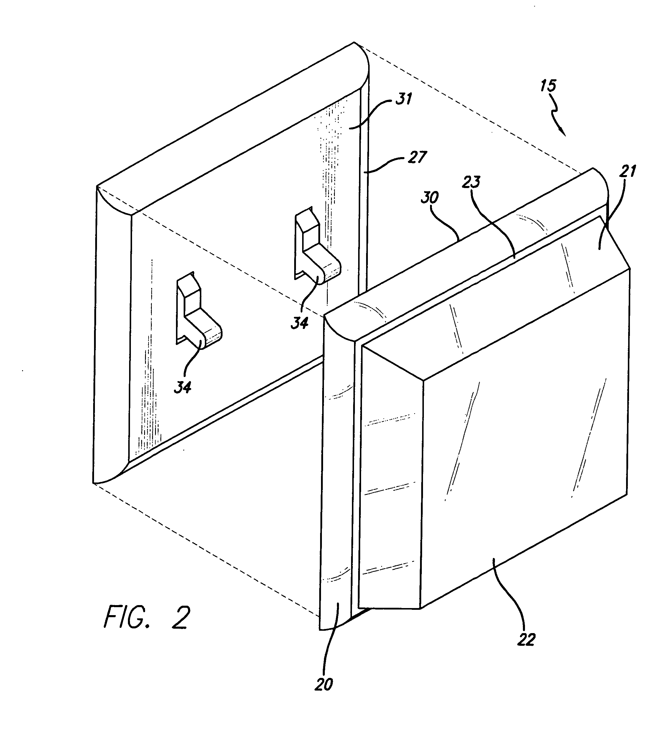
[0023]FIGS. 1 and 3 illustrate a wall plate masking or cover device 10 according to a first embodiment of the invention, while FIGS. 2 and 4 illustrate a cover device 15 of different dimensions for fitting over larger size wall plates. FIG. 5 illustrates the device 10 or 15 in use to cover an exemplary wall plate 26 or 31 while a surrounding wall surface 28 is treated by painting, plastering, applying texture, or the like.

[0024] The device 10 basically comprises a hollow housing or cover shell which has a peripheral rim 20 for fitting closely over the periphery or rim 27 of a corresponding wall plate, side walls 21 extending upwardly from the rim 20, and a raised upper wall 22 for providing clearance for items projecting outwardly from a wall plate, such as switches. The upper edge of rim 20 is rounded inwardly to form a generally flat shelf or lip 23, and the side walls 21 extend upwardly from the inner edge of lip 23 to the upper wall 22, which is flat. Both the rim 20 and lip or...


PUM


Abstract

A masking device designed to cover a wall plate during treatment of a surrounding wall surface has an open face, an outer wall spaced from the open face, and peripheral side walls extending from the periphery of the outer wall to the open face. The side walls form a peripheral rim around the open face which is of predetermined shape and dimensions for closely fitting over the peripheral rim of a selected wall plate. A layer of re-positionable adhesive is applied over the inner face of the peripheral rim for temporarily adhering the rim to the peripheral rim of the wall plate.

Description

BACKGROUND OF THE INVENTION [0001] The present invention relates generally to protection of fixtures on a surface while the surface is treated by painting, plastering, or the like, and is particularly concerned with a masking or cover device and method used for this purpose. [0002] Interior walls of buildings typically have electrical fixtures such as switches, outlets or sockets, phone jacks, and the like which are covered with relatively flat wall plates which cover the wall opening in which the fixture is mounted and which are secured to lie flat against the wall. When the wall is to be painted, plastered, or treated in some other way, such items must be covered to protect them from paint or other material. Tape such as masking tape is often used for this purpose. Wall plates are often removed prior to wall treatment, and the resultant opening covered with tape. This is both time consuming and inconvenient. [0003] Protective devices have been proposed in the past for use in cover...

Claims


Application Information

Patent Timeline
Patent Type & Authority Applications(United States)
IPC IPC(8): H02G3/14
CPCH02G3/14
Inventor TUCKER, ROBERT KENTDORIGO, FRANCESCOCOVER, ANDREW E.
Owner MERITAGE DESIGN A CALIFORNIA CORP
Learn More