Grip for golf club and golf club equipped with the same

a golf club and grip technology, applied in the field of grips for golf clubs, can solve the problems of golf clubs idly rotating in the hands of users, user's hands sliding from the grip, and difficulty in stably gripping golf clubs, and achieve the effect of improving the skill of golfers

Inactive Publication Date: 2006-12-21
LEE DOJUNG
View PDF5 Cites 20 Cited by
  • Summary
  • Abstract
  • Description
  • Claims
  • Application Information

AI Technical Summary

Benefits of technology

[0009] The present invention has been made to solve the above problems occurring in the art. Thus, it is an object of the present invention to provide a grip for a golf club, which enables a golfer to take a precise shot while realizing a long flight distance of a golf ball by allowing the golfer to stably hold the grip for the golf club while distributing centrifugal force over the whole area of the palm of the hand when the user takes a swing with the golf club, thereby preventing the hands of the golfer from being mismatched with the golf club after the swing, improving the skill of a golfer.
[0010] Another object of the present invention is to provide a grip for a golf club enabling a golfer to securely hold the grip for the golf club such that torsion may not occur in the golf club at the point of impact while standardizing the protruding degree of the grip when fabricating the grip for the golf.

Problems solved by technology

Such a structure of the grip makes it difficult for the user to stably grip the golf club so that the user may not precisely take a shot.
In addition, when taking a swing with the golf club, hands of the user may slide from the grip due to centrifugal force.
Also, the golf club may idly rotate in the hands of the user due to improper impact.
However, in this case, the centrifugal force is concentrated on the left little finger and the frictional force cannot be distributed over the entire area of the palm of the hand, which hampers close adherence between the hands and the grip.
In addition, after the grip has been fabricated through the injection molding process, it is necessary to perform sanding work to remove debris formed at the outer peripheral surface of the grip and to make the outer surface of the grip unsmooth.
However, since a worker manually performs the sanding work, it is difficult to regulate the degree of protrusion of the outer surface of the grip.
However, according to the conventional grip for the golf club, the protrusion 201 may protrude inward from the grip with a height of about 1 mm, so the outer peripheral surface of the grip may not sufficiently protrude outward from the grip even after the shaft has been inserted into the grip.
Thus, the golf club cannot sufficiently adhere to the hands of the user.

Method used


Image

  • Grip for golf club and golf club equipped with the same
  • Grip for golf club and golf club equipped with the same
  • Grip for golf club and golf club equipped with the same

Examples


Embodiment Construction

[0020] Hereinafter, the present invention will be described with reference to accompanying drawings. Wherever possible, the same reference numbers will be used throughout the drawings to refer to the same or like parts. In the following description of the present invention, a detailed description of known functions and configurations incorporated herein will be omitted when it may make the subject matter of the present invention rather unclear.

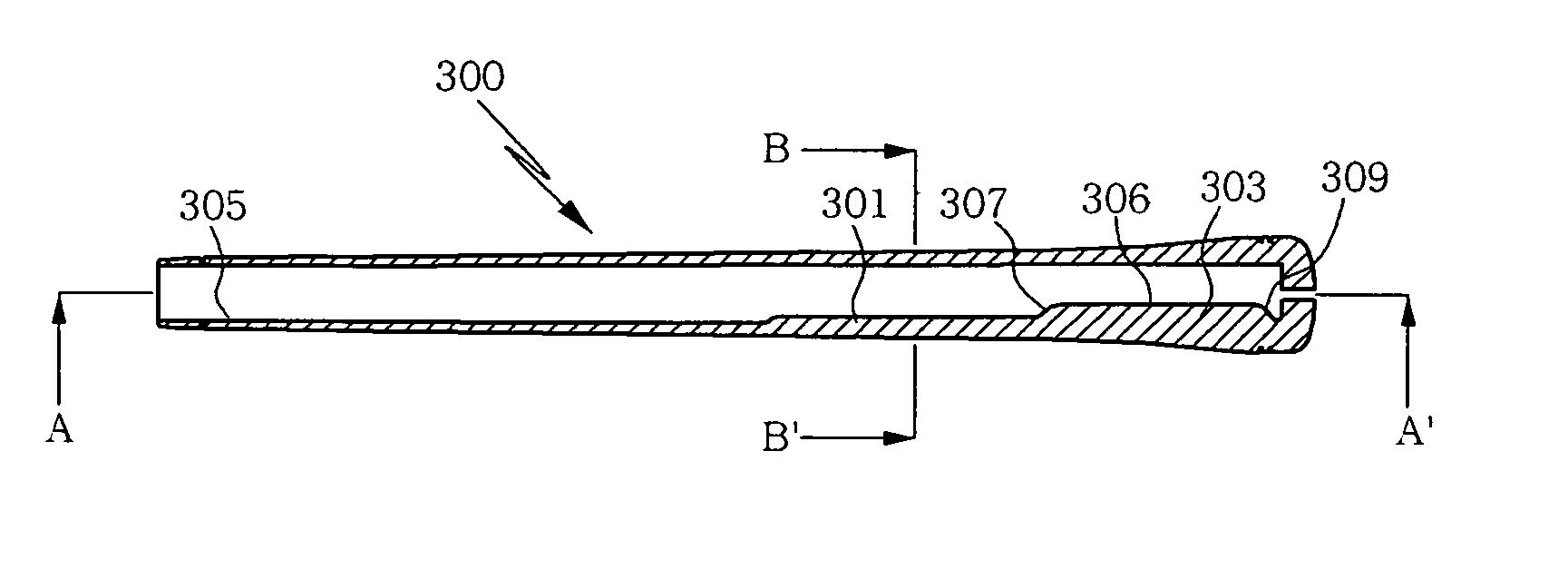
[0021]FIG. 3 is a longitudinal sectional view illustrating a grip for a golf club according to one embodiment of the present invention, FIG. 4 is a sectional view taken along line A-A′ shown in FIG. 3 and FIG. 5 is a sectional view taken along line B-B′ shown in FIG. 3.

[0022] As shown in FIGS. 3 to 5, the grip for the golf club according to one embodiment of the present invention includes: a first protrusion 301 formed at one side of an inner peripheral surface 305 of the grip while extending lengthwise along the grip by a predetermined leng...


PUM


Abstract

Disclosed are a grip and a golf club equipped with the same. The grip includes a first protrusion formed at one side of an inner peripheral surface of the grip while extending lengthwise along the grip by a predetermined distance and protruding inward from the grip, the first protrusion being biased outward as a shaft has been inserted into the grip so that an outer peripheral surface of the grip protrudes outward; and a second protrusion formed at an upper portion of the first protrusion while extending lengthwise along the grip by a predetermined distance, the second protrusion being protruded more that the first protrusion and having a width larger than that of the first protrusion, the second protrusion being biased outward as the shaft has been inserted into the grip so that the outer peripheral surface of the grip protrudes outward.

Description

RELATED APPLICATION [0001] This application is a U.S. Non-Provisional Patent Application which claims priority to Korean Patent Application No. 2005-52459, filed Jun. 17, 2005, the contents of which are hereby incorporated by reference. BACKGROUND OF THE INVENTION [0002] The present invention relates to a grip for a golf club. More particularly, the present invention relates to a grip for a golf club, in which first and second protrusions are formed at an inner peripheral surface of the grip in such a manner that the second protrusion protrudes more than the first protrusion, so, when a shaft is inserted into the grip, an outer peripheral surface of the grip protrudes outward due to physical contact between the shaft and the second protrusion so that the user can stably grip the golf club. [0003] In general, as shown in FIG. 1, a grip for a golf club has a sectional shape of circle or an oval. In addition, the grip is fabricated in such a manner that the grip has the same diameter a...

Claims


Application Information

Patent Timeline
Patent Type & Authority Applications(United States)
IPC IPC(8): A63B53/14A63B102/32
CPCA63B53/14A63B60/06A63B2102/32A63B60/10
Inventor HAN, JAEMANLEE, CHANGSEOKKIM, JEEHOON
Owner LEE DOJUNG
Why Eureka
Try Eureka