Brake booster vacuum sensor rationality check

a vacuum sensor and brake booster technology, applied in the direction of machines/engines, instruments, force/torque/work measurement apparatus, etc., can solve the problems of inability to detect all sensor failures, inability to accurately detect hi or lo signal drift failures, engine cycle into and out of dod mode in an undesirable manner,

Inactive Publication Date: 2006-12-28
GM GLOBAL TECH OPERATIONS LLC
View PDF15 Cites 19 Cited by
  • Summary
  • Abstract
  • Description
  • Claims
  • Application Information

AI Technical Summary

Benefits of technology

[0008] Accordingly, the present invention provides a vacuum signal diagnostic system that diagnoses operation of a vacuum sensor of a brake booster system that is in fluid communication with an engine. The vacuum signal diagnostic system includes a first module that determines whether a vacuum signal of the vacuum sensor is increasi...

Problems solved by technology

A faulty brake booster vacuum sensor may prevent the engine from transitioning to the deactivated mode and/or may cause the engine to cycle into and out of DOD mode in an undesirable manner.
This rationality diagnostic, however, is unable to detec...

Method used


Image

  • Brake booster vacuum sensor rationality check
  • Brake booster vacuum sensor rationality check
  • Brake booster vacuum sensor rationality check

Examples


Embodiment Construction

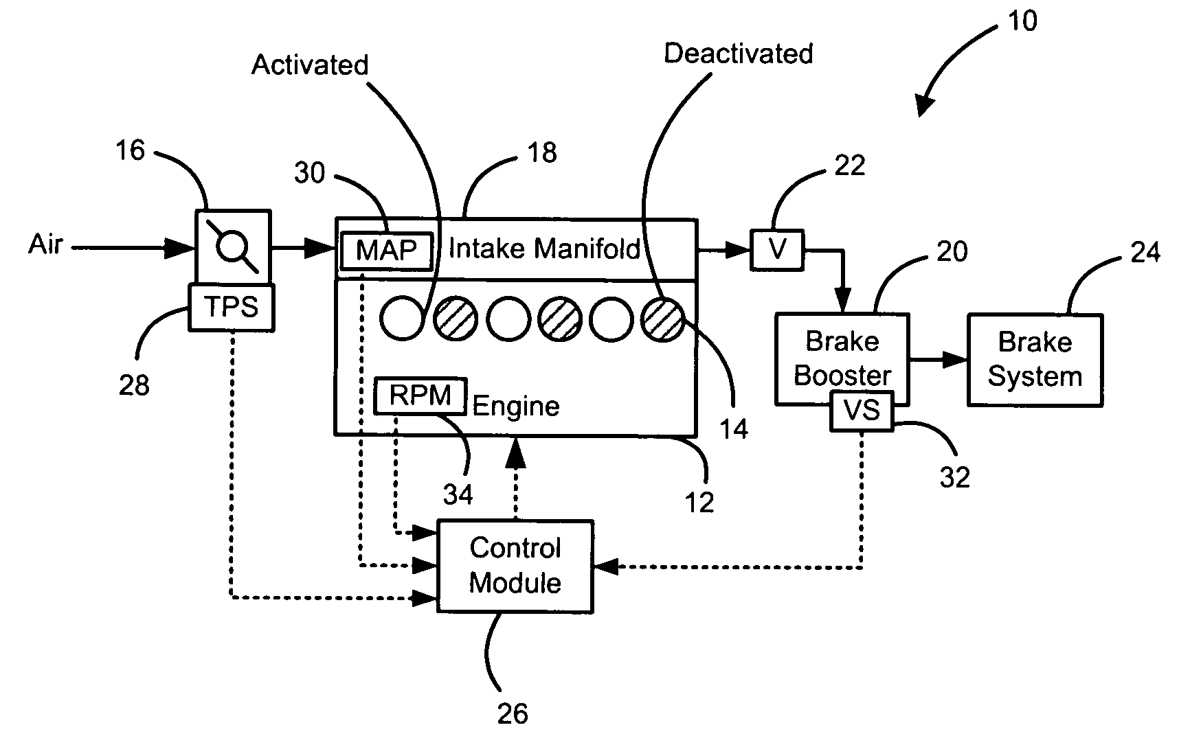
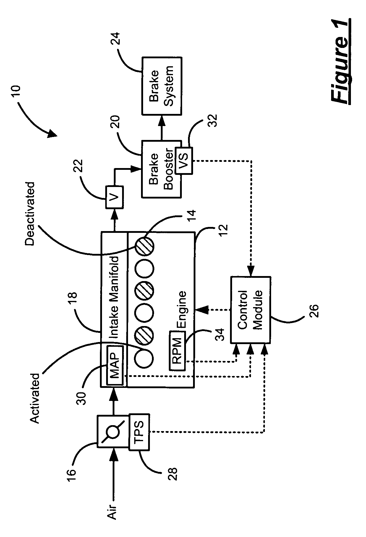
[0018] The following description of the preferred embodiments is merely exemplary in nature and is in no way intended to limit the invention, its application, or uses. For purposes of clarity, the same reference numbers will be used in the drawings to identify similar elements. As used herein, an activated mode refers to operation of the engine using all of the engine cylinders. A deactivated mode refers to operation of the engine using less than all of the cylinders of the engine (one or more cylinders not active). As used herein, the term module refers to an application specific integrated circuit (ASIC), an electronic circuit, a processor (shared, dedicated, or group) and memory that execute one or more software or firmware programs, a combinational logic circuit, and / or other suitable components that provide the described functionality.

[0019] Referring now to FIG. 1, a vehicle 10 includes an engine 12 that combusts and air and fuel mixture to generate drive torque. The engine 1...


PUM


Abstract

A vacuum signal diagnostic system that diagnoses operation of a vacuum sensor of a brake booster system that is in fluid communication with an engine includes a first module that determines whether a vacuum signal of the vacuum sensor is increasing and a second module that compares an engine vacuum signal of the engine to the vacuum signal. A third module indicates a HI fault of the vacuum sensor when the vacuum sensor is increasing and a difference between the engine vacuum signal and the vacuum signal is greater than zero for a first threshold time.

Description

CROSS-REFERENCE TO RELATED APPLICATIONS [0001] This application claims the benefit of U.S. Provisional Application No. 60 / 690,163, filed on Jun. 13, 2005. The disclosure of the above application is incorporated herein by reference.FIELD OF THE INVENTION [0002] The present invention relates to vehicles using brake booster vacuum sensors, and more particularly to a rationality check of a vacuum signal generated by the brake booster vacuum sensor. BACKGROUND OF THE INVENTION [0003] Vehicles systems can include an internal combustion engine that combusts an air and fuel mixture to produce drive torque. The drive torque is transmitted to a drivetrain to accelerate the vehicle. A brake system is also included and is operable to decelerate the vehicle by applying brake pressure to brakes. In some vehicle systems, a brake booster is provided to reduce braking effort. More specifically, the brake booster increases the force applied to a master cylinder of the brake system using a brake boost...

Claims


Application Information

Patent Timeline
IPC IPC(8): G01L5/13
CPCG01L27/007
Inventor WANG, ZHONGWANG, WENBOANILOVICH, IGORVAN GILDER, JOHN
Owner GM GLOBAL TECH OPERATIONS LLC
Why Eureka
Try Eureka