
Collateral Cavity Electromagnetic Propulsion Guns

Inactive Publication Date: 2006-12-28
FRASCA JOSEPH FRLIN
View PDF6 Cites 5 Cited by
  • Summary
  • Abstract
  • Description
  • Claims
  • Application Information

AI Technical Summary

Benefits of technology

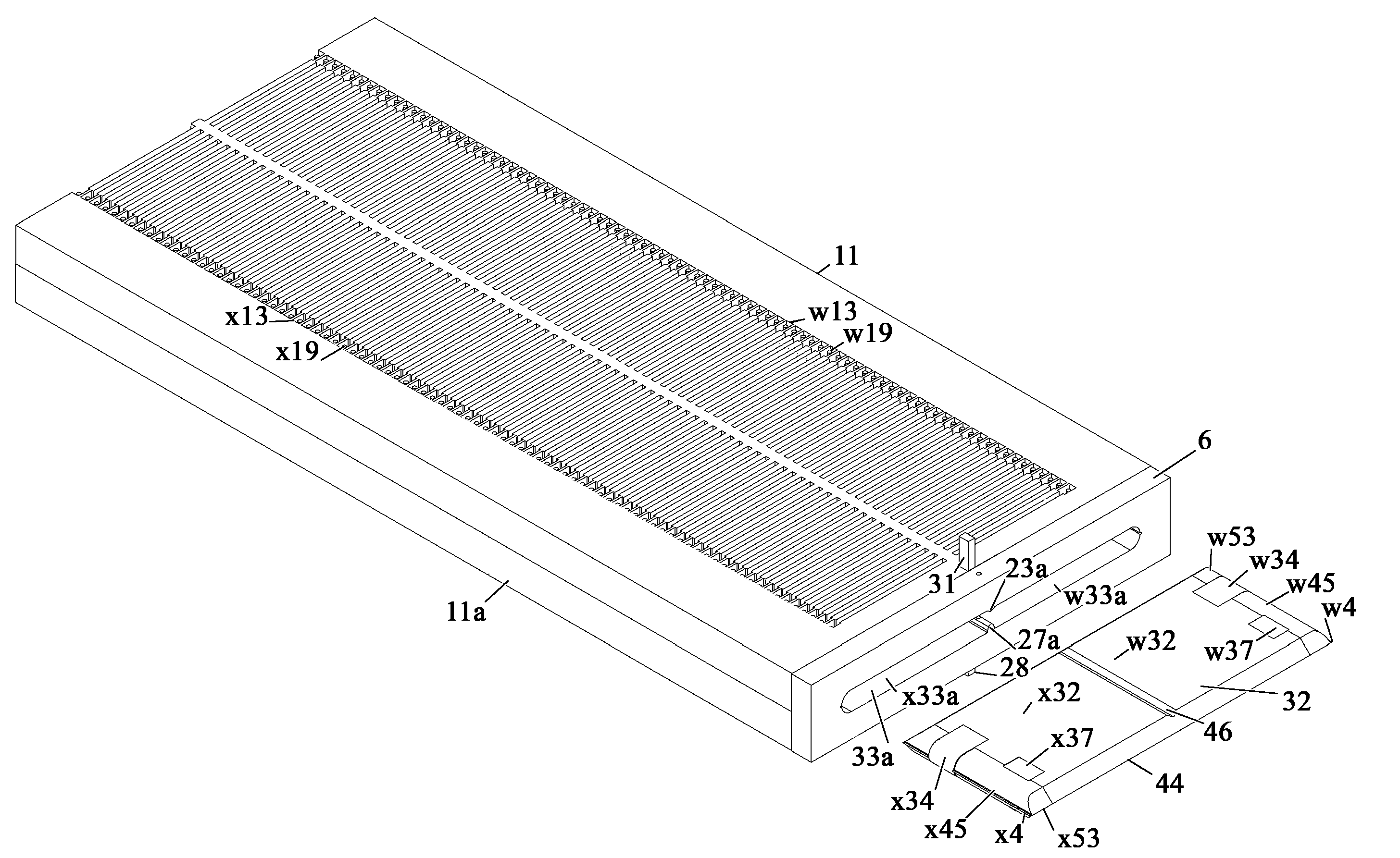
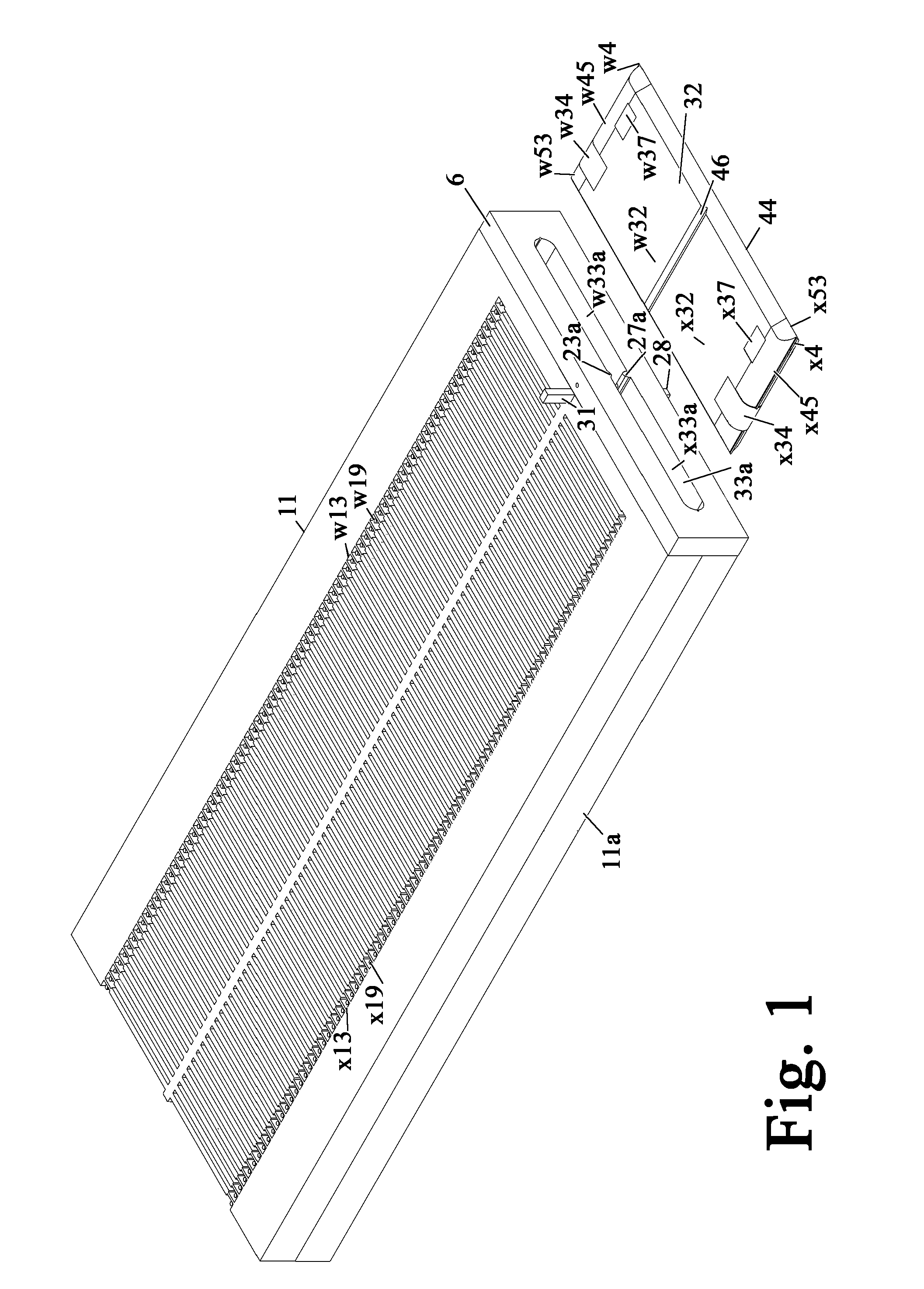
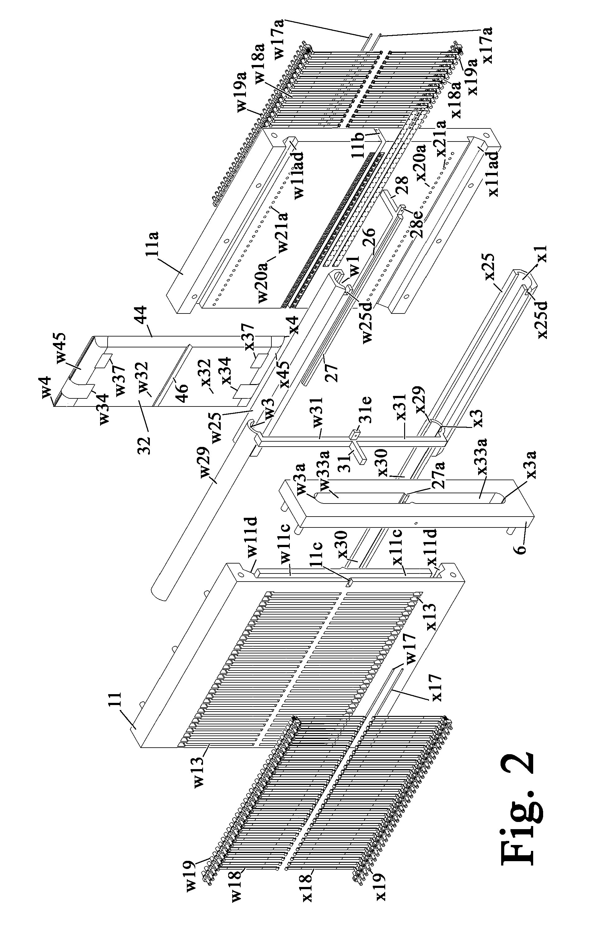
[0016] The collateral barrel cavity of the topic invention and the projectiles used therein eliminate the above said losses due to friction by utilizing like, but oppositely directed forces of attraction between the current buses in each collateral half of a projectile and their proximal power rail which cancel each other and the need of additional barrel rails and their attendant sliding continuities to avoid said loss generating force is eliminated.

Problems solved by technology

These devices, although more cumbersome, permits more latitude in accelerator design.

Method used


Image

  • Collateral Cavity Electromagnetic Propulsion Guns
  • Collateral Cavity Electromagnetic Propulsion Guns
  • Collateral Cavity Electromagnetic Propulsion Guns

Examples


Embodiment Construction

[0028] Devices of this invention are electromagnetic propulsion guns that have a barrel with a narrow cavity, the barrel cavity, extending there through. The barrel cavity has a breech end opening at one barrel end and a muzzle end opening at the other barrel end and a central axis extending said cavity's length which is parallel to the cavity's surfaces.

[0029] Disregarding slight variations in the cavity's profiles in barrel cavity right sections taken at the openings in the barrel cavity walls for wall conductor's contact means and said means therein, right sections taken to the central cavity axis throughout the cavity are alike; i.e. cavity's profiles in right section planes to said cavity axis are alike.

[0030] The cavity's central axis is through the centroid centers of the cavity's profile in said right sections. Generally the central axis of an element is the line through the centroid centers of right sections taken through said element along a path in which said element's ...


PUM


Abstract

Narrow collateral cavity electromagnetic guns with two wall conductor assemblies with a divide plane proximal barrel bus and array of wall conductors extending therefrom to contact means proximal the half cavity's narrow wall in each collateral cavity half, like potential power rails at the narrow walls and a midline power rail in a wall there between. Each collateral half of projectiles for use therein have: a propulsion bus orthogonal the cavity's axis continuous the said midline power rail at one end and propulsion bus-aft shunt current bus the other, and forward and aft current shunts on both sides of the projectile's collateral halves. Projectile's current buses co-act with said assembles, shunts and power rails circulating the gun's current around both sides of the propulsion buses and the magnet fields of said circuit interact with the propulsion buses' currents creating forces therein propelling the projectile through the barrel cavity.

Description

CROSS REFERENCE TO RELATED APPLICATIONS [0001] This application is a divisional application of patent application Ser. No. 10 / 707,607 filed Dec. 24, 2003 and claims the benefit of the filing dates of provisional patent application 60 / 319,820 filed Dec. 30, 2002, provisional patent application 60 / 320,208 filed May 21, 2003, and provisional patent application 60 / 481,159. This application is also related to sister divisional application Ser. No. 11 / 164,727 filed Dec. 2, 2005 and sister divisional application Ser. No. 11 / 306,245 filed Dec. 20, 2005.BACKGROUND OF THE INVENTION [0002] 1. Field of the Invention [0003] The following invention is related electromagnetic propulsion devices such as rail guns. In rail guns a magnetic field perpendicular to an electrical current path through an armature, interacts with the path current, creating force on the armature which is perpendicular to both the current path and the magnetic field. The armature of a rail gun is located between and has ele...

Claims


Application Information

Patent Timeline
IPC IPC(8): F41B6/00
CPCF41B6/00F41B6/006F41B6/003
Inventor FRASCA, JOSEPH FRANKLIN
Owner FRASCA JOSEPH FRLIN
Learn More