Tactile feedback system
a tactile feedback and feedback technology, applied in the field of tactile feedback systems, can solve problems such as the challenge of applying vibration tactile feedback
- Summary
- Abstract
- Description
- Claims
- Application Information
AI Technical Summary
Benefits of technology
Problems solved by technology
Method used
Image
Examples
first embodiment
[0069]the present disclosure is described below.
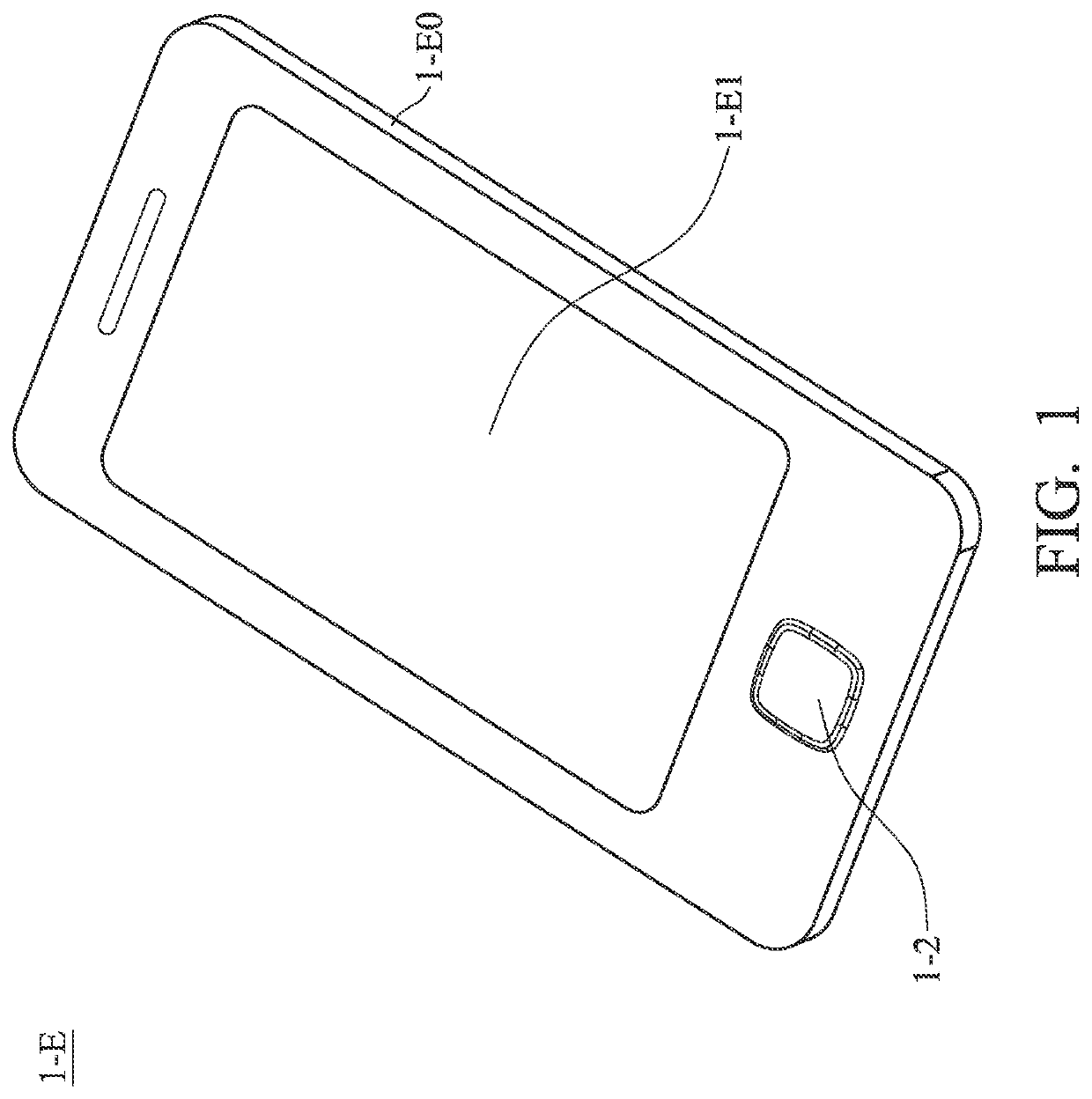
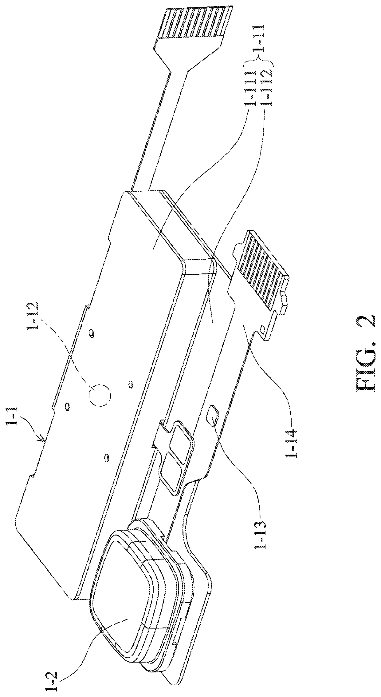
[0070]FIG. 1 is a perspective diagram of an electronic device 1-E in accordance with an embodiment of the invention. FIG. 2 is a perspective diagram of a tactile feedback system 1-1 and a sensing module 1-2 disposed in the electronic device 1-E of FIG. 1.
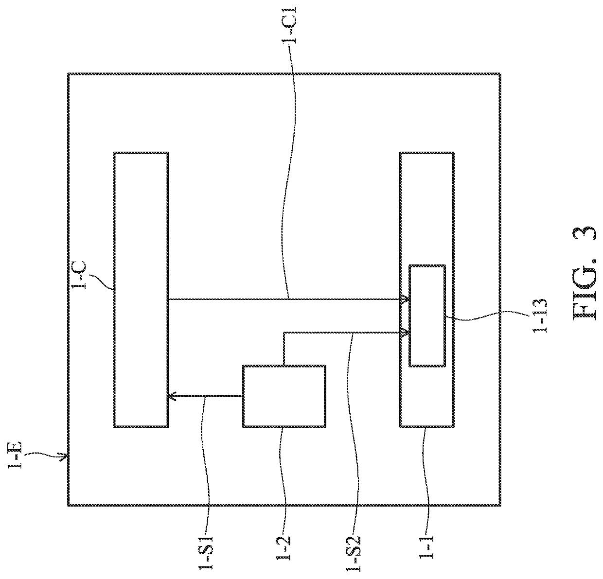
[0071]Referring to FIGS. 1 and 2, the electronic device 1-E in this embodiment may be a cell phone or a tablet computer that comprises a housing 1-E0 and a screen 1-E1 disposed on the housing 1-E0. Specifically, a sensing module 1-2 is disposed on a lower side of the housing 1-E0. The sensing module 1-2 may constitute at least a part of a touch pad, a button or other user interface of the electronic device 1-E. In some embodiments, the sensing module 1-2 may comprise an Optical Finger Navigation (OFN) sensor, gyroscope, accelerometer, tactile switch, fingerprint sensor, pressure sensor, sound wave sensor, gas sensor, temperature sensor, or gas concentration sensor, not limited to the e...
second embodiment
[0092]the present disclosure is described below.
[0093]The optical component driving mechanism of the embodiment of the present invention is described below. However, it can be easily understood that the embodiments of the present invention provide many suitable inventive concepts and can be implemented in a wide variety of specific backgrounds. The specific embodiments disclosed are only used to illustrate the use of the present invention in a specific method, and are not used to limit the scope of the present invention. Unless otherwise defined, all terms used here (including technical and scientific terms) have the same meanings commonly understood by the general artisans to whom the disclosures in this article belong. It is understandable that these terms, such as the terms defined in commonly used dictionaries should be interpreted as having a meaning consistent with the relevant technology and the background or context of this disclosure, and should not be interpreted in an ide...
third embodiment
[0163]the present disclosure is described below.
[0164]Refer to FIG. 21A. FIG. 21A is a schematic view of an optical module 3-1001 in some embodiments of the present disclosure. The optical module 3-1001 may mainly include a light amount adjusting mechanism 3-1100 and an optical element driving mechanism 3-1200. An optical element 3-1230 may be disposed in the optical element driving mechanism 3-1200, and the optical element driving mechanism 3-1200 may drive the optical element 3-1230 to achieve optical image stabilization (OIS) or auto focus (AF). The light amount adjusting mechanism 3-1100 may be disposed on the optical element driving mechanism 3-1200 to control the amount or characteristic of light incident to the optical element 3-1230. For example, the light amount adjusting mechanism 3-1100 may be an aperture to control the depth of field, imaging quality, and amount of light coming in.
[0165]In some embodiments, the optical element 3-1230 may include a lens, a mirror, a prism...
PUM
 Abstract
Description
Claims
Application Information
 - R&D
- Intellectual Property
- Life Sciences
- Materials
- Tech Scout
- Unparalleled Data Quality
- Higher Quality Content
- 60% Fewer Hallucinations
Browse by: Latest US Patents, China's latest patents, Technical Efficacy Thesaurus, Application Domain, Technology Topic, Popular Technical Reports.
© 2025 PatSnap. All rights reserved.Legal|Privacy policy|Modern Slavery Act Transparency Statement|Sitemap|About US| Contact US: help@patsnap.com


