Holder for electronic apparatus

a technology for holding devices and electronic devices, which is applied in the direction of stands/trestles, instruments, vehicle components, etc., can solve the problems of inability to provide a large screen for user viewing, inconvenient viewing for users, and user inconvenience,

Inactive Publication Date: 2006-12-28
WANG CHIN YANG
View PDF3 Cites 68 Cited by
  • Summary
  • Abstract
  • Description
  • Claims
  • Application Information

AI Technical Summary

Benefits of technology

[0007] It is an object of the present invention to provide a holding device comprising a support having its underside attached to a seat and a top surface adapted to hold an electronic apparatus (e.g., PDA or cellular phone); a shuttle member having one end slidably passed one end of the support; a pivot at the other end of the shuttle member; a magnifying glass having one end pivotally connected to the pivot such that the magnifying glass is adapted to turn a predetermined angle about the pivot; and a catch at one ends of the support and the shuttle member for lockably engaging the shuttle member or not. By utilizing this holding device, it is possible of adjusting a distance of the magnifying glass relative to a display of the electronic apparatus on the support, thereby enabling a user to see a magnified, clear display through the magnifying glass. Moreover, the drawback of the prior holder (e.g., a user is unable to see a magnified, clear display of the electronic apparatus on the support) is substantially eliminated by the present invention.

Problems solved by technology

Thus, it is impossible of doing without them.
Also, a display 151 of the electronic apparatus 15 is relatively small and thus it is impossible of providing a large screen for user viewing.
Thus, a user may often feel inconvenient and be bothered in watching display 151 for understanding his / her exact position, deciding route of a proposed journey, or plotting destination on the map.

Method used


Image

  • Holder for electronic apparatus
  • Holder for electronic apparatus
  • Holder for electronic apparatus

Examples


Embodiment Construction

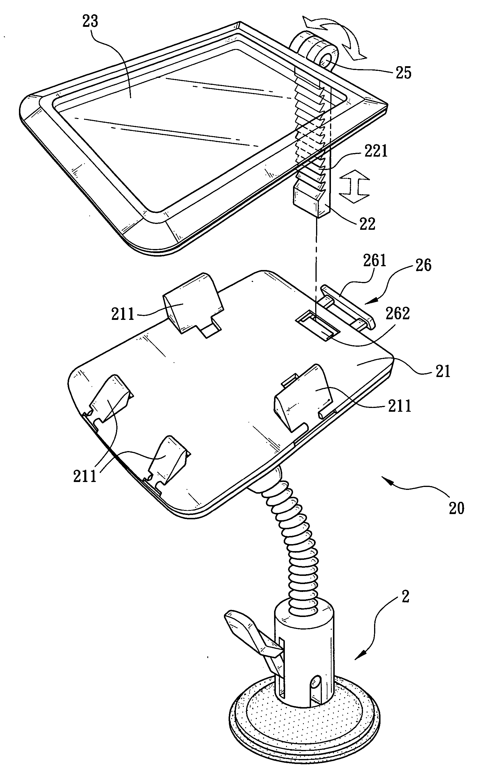
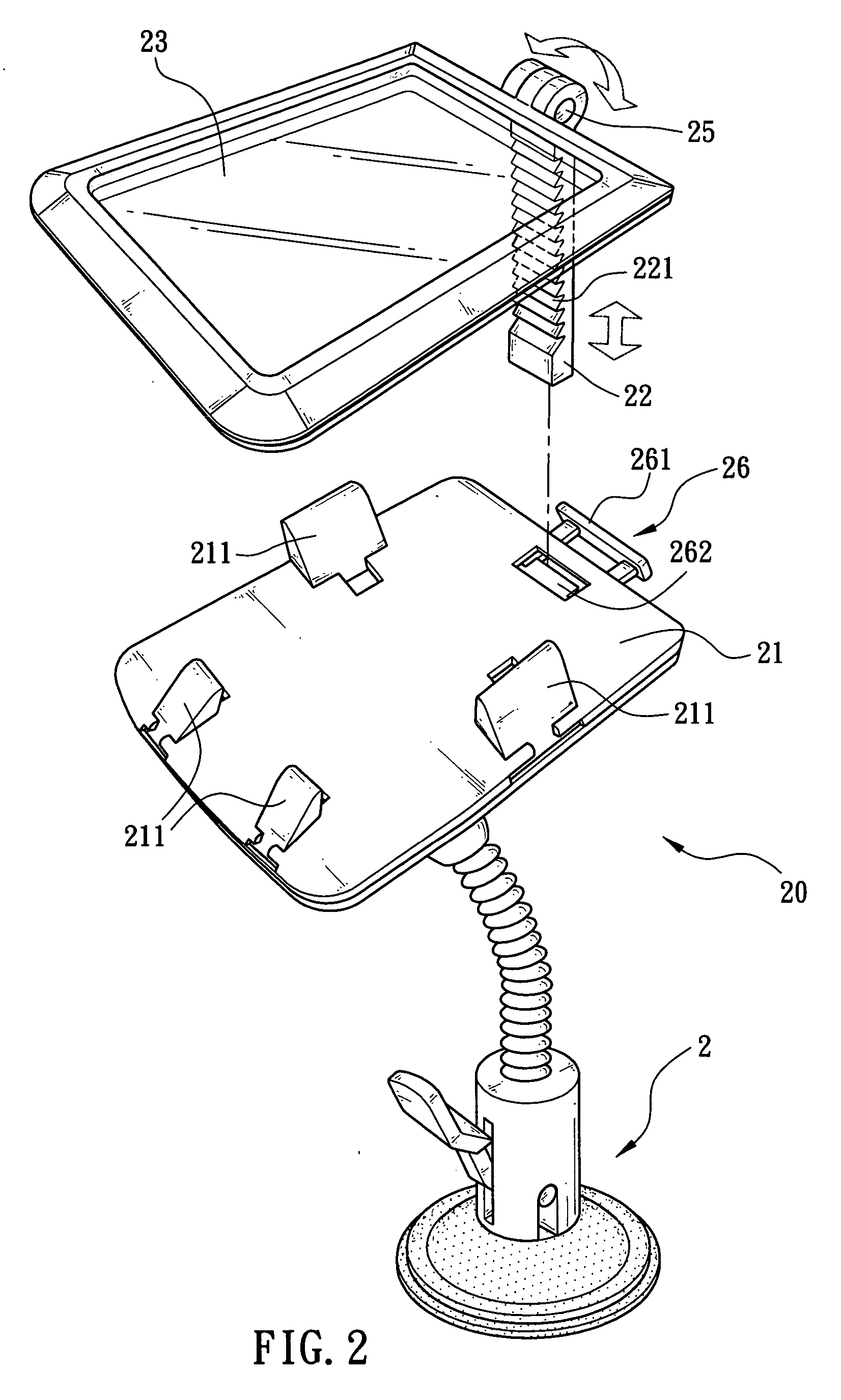
[0016] Referring to FIG. 2, there is shown a holder 20 for electronic apparatus according to a first preferred embodiment of the invention. The holder 20 comprises a support 21, a shuttle member 22, and a magnifying glass 23. The underside of the support 21 is attached to a seat 2 secured to a flat surface (e.g., console of an automobile). A top surface of the support 21 is adapted to hold an electronic apparatus 42 (e.g., a PDA or cellular phone as shown in FIG. 5). The shuttle member 22 has one end slidably passed one end of the support 21 and the other end connected to a pivot 25 attached to one end of the magnifying glass 23. Thus, the magnifying glass 23 may turn a predetermined angle about the pivot 25. Also, a catch 26 is provided at one end of the support 21. The catch 26 has a trigger 261 adapted to lockably engage the shuttle member 22 or not for adjusting a distance of the magnifying glass 23 relative to a display 421 of the electronic apparatus 42 on the support 21 (see ...


PUM


Abstract

The present invention is to provide a holding device comprising a support having its underside attached to a seat and a top surface adapted to hold an electronic apparatus; a shuttle member having one end slidably passed one end of the support; a pivot at the other end of the shuttle member; a magnifying glass having one end pivotally connected to the pivot such that the magnifying glass is adapted to turn a predetermined angle about the pivot; and a catch at one ends of the support and the shuttle member for lockably engaging the shuttle member, for adjusting a distance of the magnifying glass relative to a display of the electronic apparatus on the support and enabling a user to see a magnified, clear display through the magnifying glass.

Description

FIELD OF THE INVENTION [0001] The present invention relates to holding devices and more particularly to a device having one end attached to a member (e.g., console) of an automobile and the other end with an electronic apparatus (e.g., PDA (personal digital assistant)) firmly held thereon. BACKGROUND OF THE INVENTION [0002] The world we are living in has entered into a new era due to rapid progress of electronics and computer technologies. A wide variety of electronic products are available in an even faster pace in recent years. The fast development of electronic products not only brings a lot of convenience but also improves living quality. As a result, such products are closely associated with our daily life and work. An important one of the electronic products is PDA and which is a pocket-sized computer with features such as being compact, lightweight, and fast in processing speed. Moreover, PDA can incorporate features such as notebook, calendar, database, video game, telephone...

Claims


Application Information

Patent Timeline
Patent Type & Authority Applications(United States)
IPC IPC(8): G09G5/00
CPCB60R11/0235F16M13/022B60R2011/0056B60R2011/0071B60R2011/0082B60R2011/0084B60R2011/0085F16M11/40F16M13/02F16M11/041F16M11/10F16M11/2092F16M11/24F16M13/00B60R11/0252
Inventor WANG, CHIN-YANG
Owner WANG CHIN YANG
Why Eureka
Try Eureka