Tomographic mammography method

a mammography and tomography technology, applied in the field of imaging system, can solve the problems of unsatisfactory high x-ray exposure dose for patients, large vibration of x-ray sources, and large complexity of algorithm

Inactive Publication Date: 2006-12-28
GENERAL ELECTRIC CO
View PDF11 Cites 105 Cited by
  • Summary
  • Abstract
  • Description
  • Claims
  • Application Information

AI Technical Summary

Problems solved by technology

If a human patient is being imaged, repeated scans cause an undesirably high X-ray exposure dose for the patient.
However, while this tomosynthesis system is capable of forming adequate three dimensional mammography images, it suffers from several disadvantages.
This algorithm adds complexity to the image processing.
Furthermore, the X-ray source is subject to a large amount of vibration because the system operates in a “step and shoot” mode, which distorts and blurs the image.
The start and stop motion of the X-ray source causes the X-ray source to vibrate during the sudden stops, which causes the X-ray beam to be displaced relative to the object and to increase the blurring of the image.

Method used


Image

  • Tomographic mammography method
  • Tomographic mammography method
  • Tomographic mammography method

Examples


first embodiment

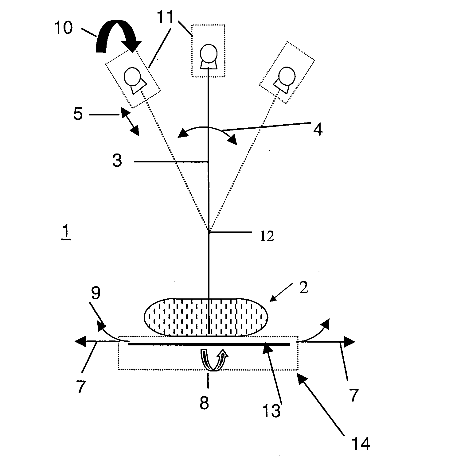
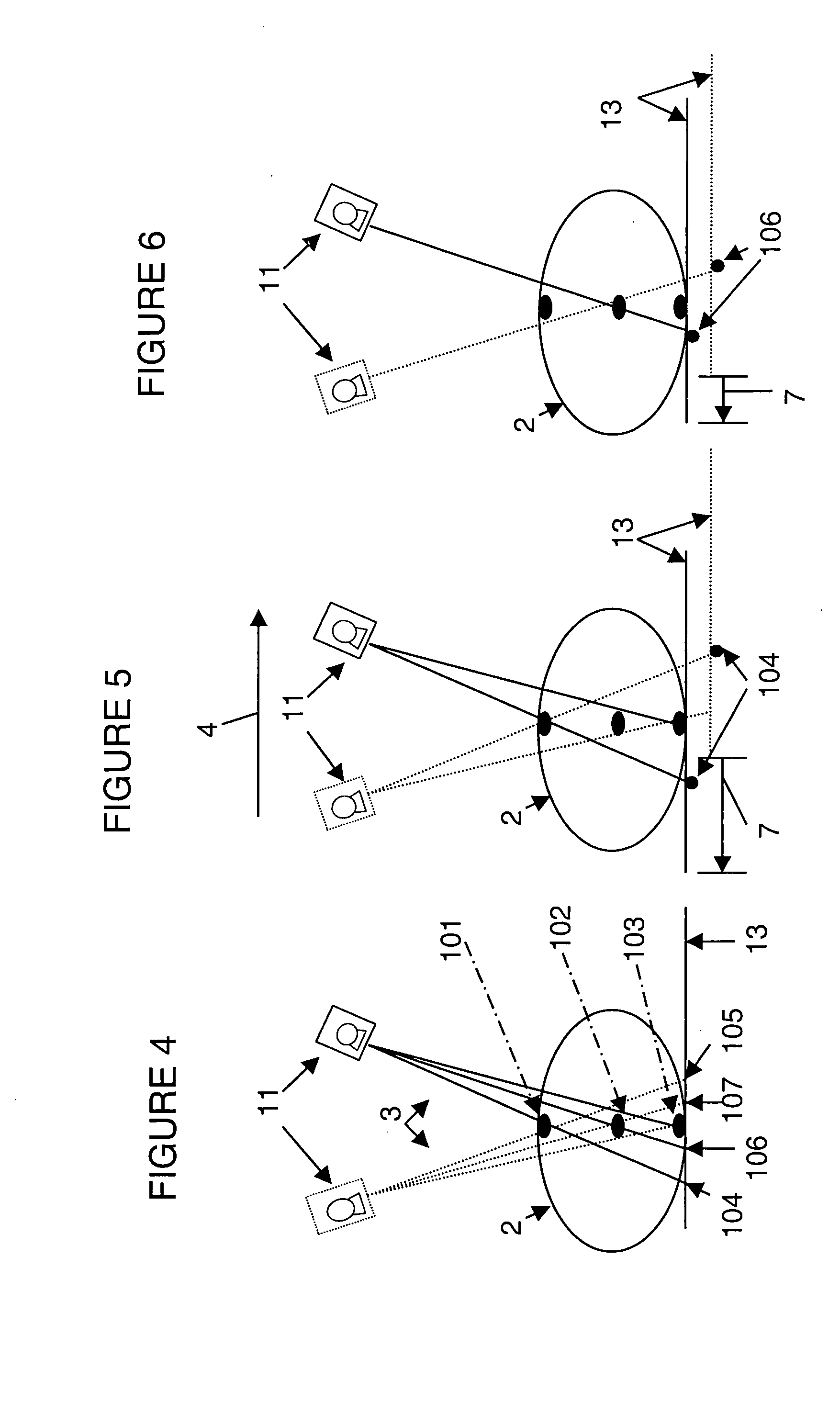
[0022] Translating the detector 13 in an opposite direction from the rotation direction of the X-ray source 11 allows the detector 13 to be generally opposite of the X-ray source with respect to the imaged object 2 and allows the X-ray beams 3 to be incident on the detection surface of the detector 13. Thus, in the first preferred aspect of the first embodiment, the detector 13 is translated incrementally in the second direction along path 7 while the X-ray source 11 moves incrementally in the first direction along path 4, to ensure that the X-ray beam 3 is always incident on the detector 13 surface. Before a new image acquisition, and after a previous image acquisition, the detector 13 and the X-ray source 11 move to suitable start positions. In this embodiment, the detector 13 and the X-ray source 11 preferably remain stationary while the X-ray source 11 emits a shot (i.e., a beam of X-rays 3 such that the system 1 operates in the “step and shoot” mode). The detector 13 and the X-...

second embodiment

[0038] In a second preferred embodiment of the present invention, the X-ray source 11 irradiates the object 2 with the beam of X-rays 3 such that a focal point of the beam of X-rays follows a non arc shaped path relative to the detector 13. The preferred aspects of the second embodiment are described below.

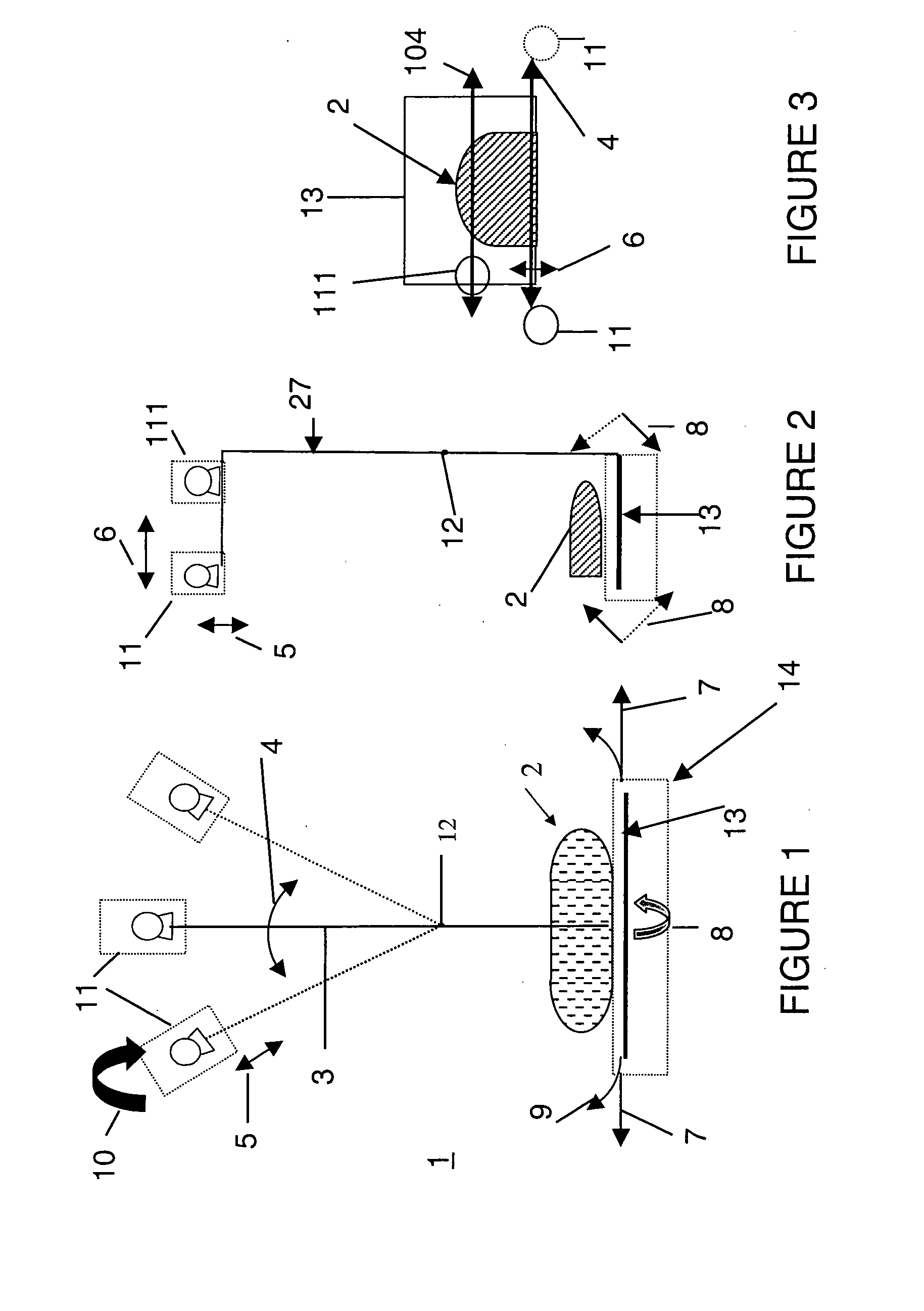
[0039] In a first preferred aspect of the second embodiment, the X-ray source 11 rotates in a first angular direction along the rotational path 4 and the focal point of the X-ray beam moves along with the X-ray source and also moves in a second direction substantially along the redirection (i.e., the radial direction), as shown by path 5 in FIGS. 1 and 2. The X-ray beam focal point may be moved in the r-direction by moving the X-ray source in the redirection along path 5, by changing the position of an electron beam focal spot on an X-ray target located in the X-ray tube located in the X-ray source 11 and / or by using an X-ray lens.

[0040] For example, the X-ray source 11 may be me...

fifth embodiment

[0051] In a fifth preferred embodiment of the present invention, two or more X-ray sources are used. In a first preferred aspect of the fifth embodiment, at least two X-ray sources 11, 111 rotate in respective arc shaped paths 4, 104. In one embodiment, the paths 4, 104 in their respective parallel planes are offset from each other in the y-direction 6 (i.e., in a direction perpendicular to the rotation planes), as shown in FIGS. 2 and 3. The sources 11, 111 may rotate in the same direction or in opposite directions along paths 4, 104. Thus, second X-ray source 111 rotates in a plane farther from the patient chest wall 20 than the first X-ray source 11. If the sources 11, 111 rotate in the same direction, then preferably, the first X-ray source 11 is also offset from the second X-ray source 111 in the rotation direction (i.e., along path 4) during rotation in the arc shaped path. The second X-ray source 111 also moves ahead or behind the first X-ray source 11 along its rotation path...


PUM

PropertyMeasurementUnit
projection anglesaaaaaaaaaa
degree of freedomaaaaaaaaaa
sizeaaaaaaaaaa

Abstract

A tomosynthesis system for forming a three dimensional image of an object is provided. The system includes an X-ray source adapted to irradiate the object with a beam of X-rays from a plurality of positions in a sector, an X-ray detector positioned relative to the X-ray source to detect X-rays transmitted through the object and a processor which is adapted to generate a three dimensional image of the object based on X-rays detected by the detector. The detector is adapted to move relative to the object and / or the X-ray source is adapted to irradiate the object with the beam of X-rays such that the beam of X-rays follows in a non arc shaped path and / or a center of the beam of X-rays impinges substantially on the same location on the detector from different X-ray source positions in the sector.

Description

BACKGROUND OF THE INVENTION [0001] The present invention relates generally to an imaging system, and more particularly to an X-ray tomosynthesis mammography imaging system. [0002] X-ray motion tomography is an X-ray imaging method in which an X-ray tube and a detector move in opposite directions relative to a patient or another object that is being imaged. In tomography, X-rays beams are turned on while the X-ray tube and the detector are in motion, thereby selecting a single in-focus plane and blurring out all others. However, tomography is used to image only a single in-focus slice of the object being imaged rather than a three dimensional volume of the object being imaged. To image other slices of the object, additional scans of the X-ray tube and detector are needed. If a human patient is being imaged, repeated scans cause an undesirably high X-ray exposure dose for the patient. [0003] X-ray mammography is the modality of choice for breast cancer screening. U.S. Pat. No. 5,872,8...

Claims


Application Information

Patent Timeline
Patent Type & Authority Applications(United States)
IPC IPC(8): H05G1/60A61B6/00G01N23/00G21K1/12A61B6/02A61B6/03
CPCA61B6/025A61B6/032A61B6/4014A61B6/4028A61B6/4429A61B6/502A61B6/4266
Inventor EBERHARD, JEFFREY WAYNECLAUS, BERNHARD ERICH HERMANNLANDBERG, CYNTHIA ELIZABETHMULLER, SERGE LOUIS WILFRIDDELMAS, YANNWIRTH, REINHOLD FRANZMORROW, JAMES GEORGE
Owner GENERAL ELECTRIC CO
Why Eureka
Try Eureka