Breast imaging method and system

a technology of breathing and imaging method, applied in the field of breathing cancer screening, can solve the problems of limiting the ability of a diagnostician to visualize, affecting the accuracy of breathing, so as to achieve good in-plane resolution and, potentially, poor depth resolution

Active Publication Date: 2016-06-16
GENERAL ELECTRIC CO
View PDF3 Cites 73 Cited by
  • Summary
  • Abstract
  • Description
  • Claims
  • Application Information

AI Technical Summary

Benefits of technology

[0007]In one embodiment, a breast imaging system is provided. The breast imaging system includes: a frame structure comprising an open region; an ultrasound probe attached to the frame structure and configured to move along the frame structure over the open region during operation; and one or more pivot structures about which the frame structure is configured to pivot with respect to a compression paddle.
[0008]In a further embodiment, a breast imaging system is provided. The breast imaging system includes: a frame structure comprising an open region and one or more engagement structures. The breast imaging system also includes: a removable ultrasound probe comprising one or more complementary structures configured to engage and disengage the engagement structures, wherein the ultrasound probe is configured to move along the frame structure over the open region during operation.

Problems solved by technology

Such approaches, however, may suffer from various detriments.
For example, conventional radiographic imaging techniques are generally planar or two-dimensional in nature, limiting the ability of a diagnostician to visualize the results.
In general, tomosynthesis imaging exhibits good in-plane resolution with, potentially, poorer depth resolution.
However, one impediment to the design and use of such systems in this manner is the interference that the various parts of one systems may have on the other system, such as the presence of an ultrasound probe in the vicinity of the X-ray beam path, and the need to minimize or coordinate the operations to be performed by the attending technologist.

Method used


Image

  • Breast imaging method and system
  • Breast imaging method and system
  • Breast imaging method and system

Examples


Embodiment Construction

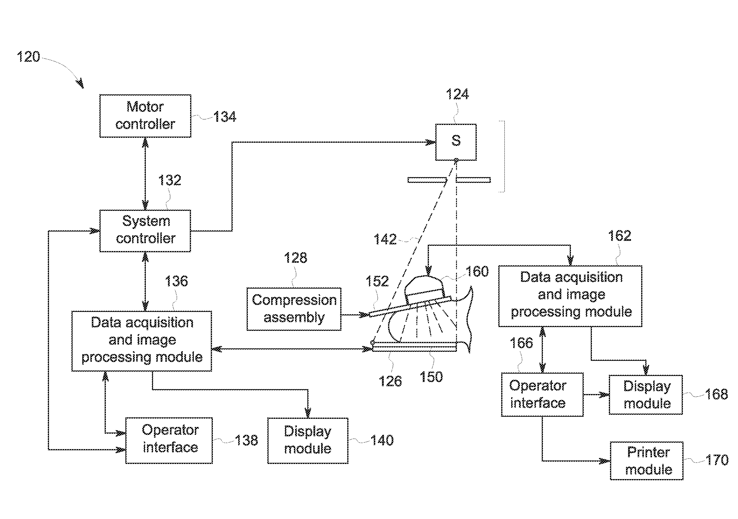
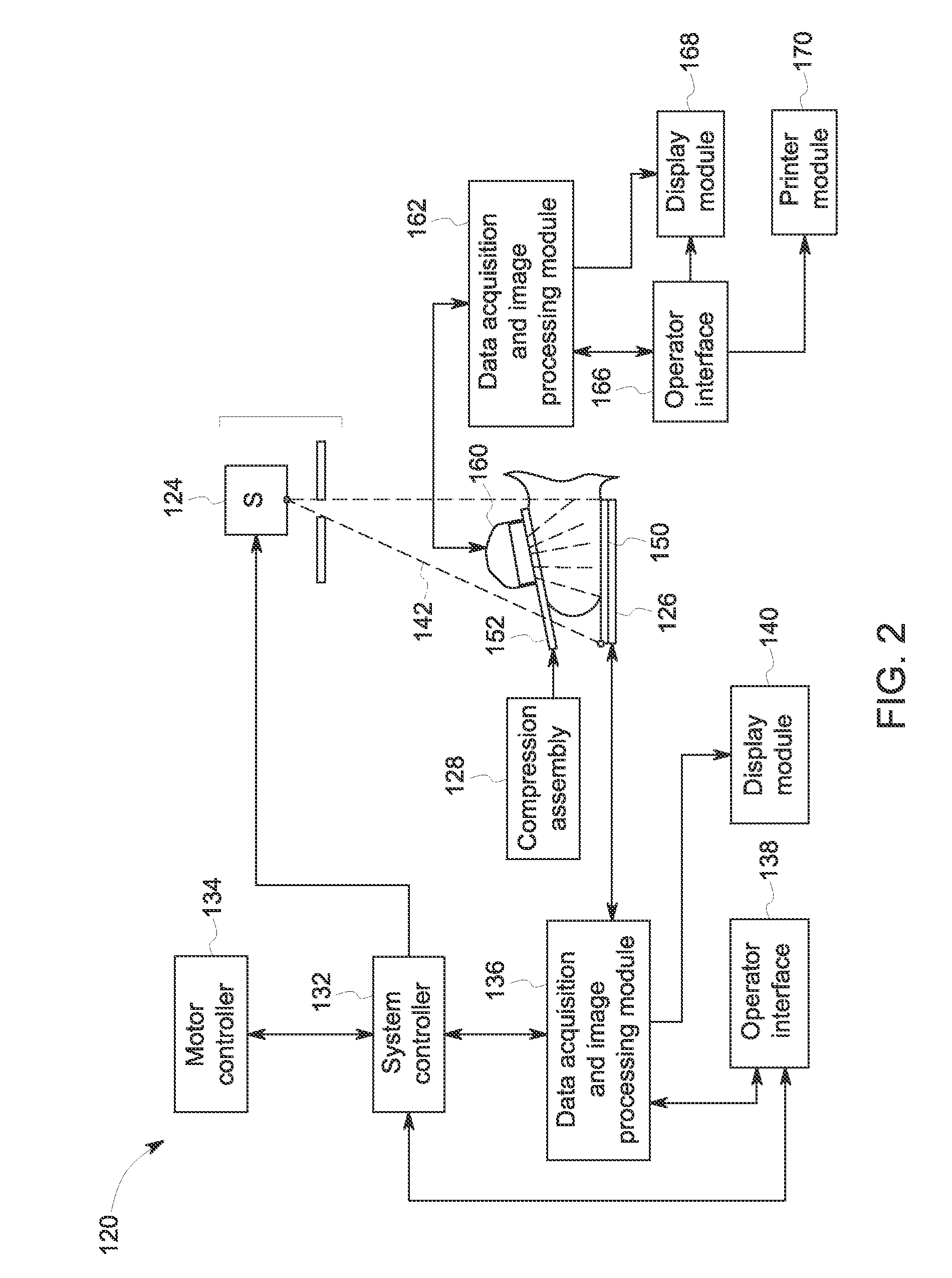
[0020]The present approach is directed towards acquisition of breast image data, such as the acquisition of ultrasound breast image data. For example, in certain embodiments, an automated ultrasound scanning system is described which may be used to implement a pre-programmed scan protocol in an automated manner. Such scans may be performed by moving an ultrasound probe across the breast tissue of a patient without user intervention or guidance during the scan operation.

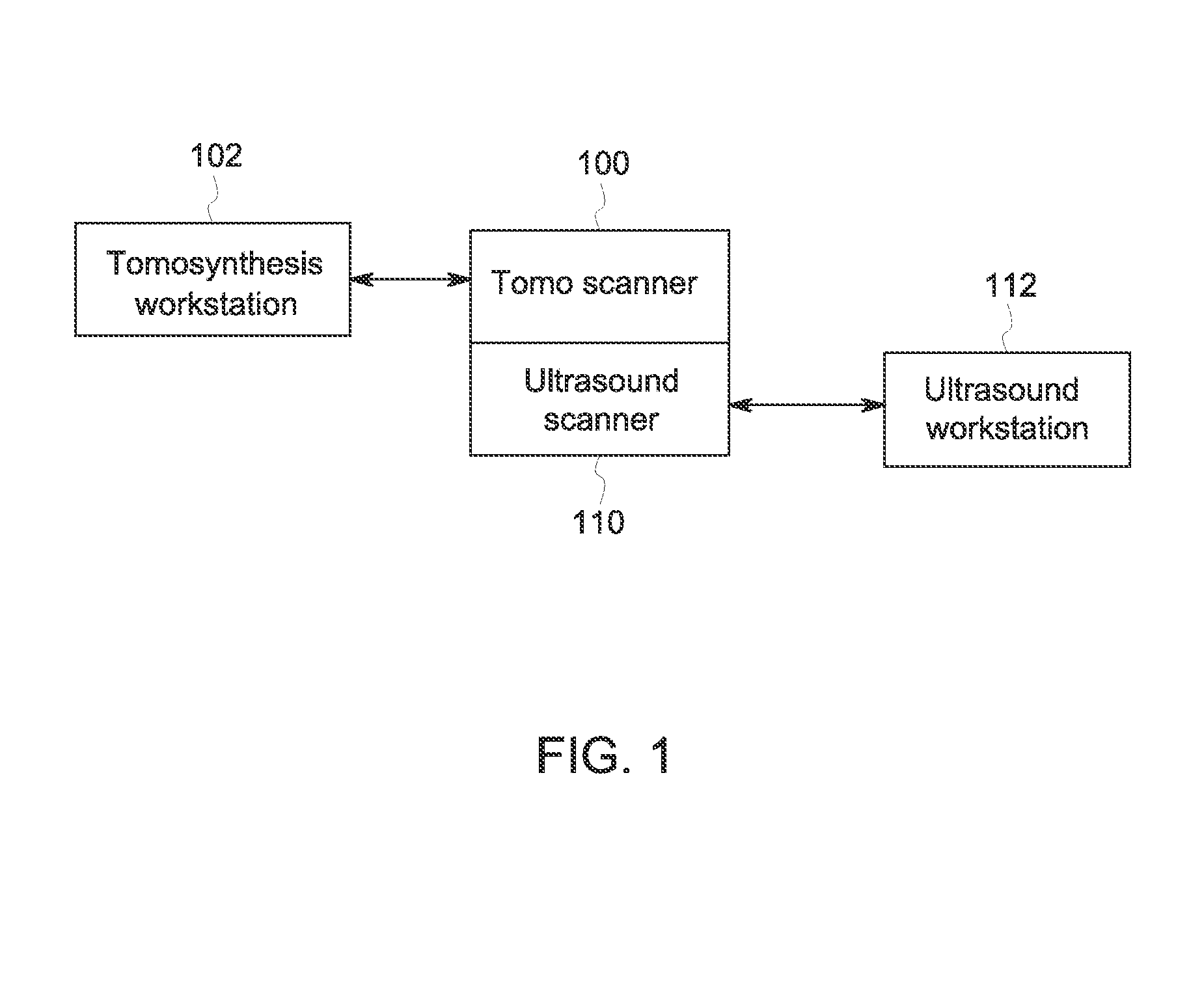
[0021]In certain embodiments discussed herein, the ultrasound scan probe and support mechanism are configured to be used in a multi-modality mammography imaging system, such as a combined tomosynthesis and ultrasound imaging system. For example, in such an embodiment, the ultrasound components may be positioned and configured so as not to interfere with the tomosynthesis imaging operation, such as to remain out of the X-ray beam path. Further, the ultrasound probe and associated components may be configured to as to m...


PUM


Abstract

An ultrasound scan probe and support mechanism are provided for use in a multi-modality mammography imaging system, such as a combined tomosynthesis and ultrasound imaging system. In one embodiment, the ultrasound components may be positioned and configured so as not to interfere with the tomosynthesis imaging operation, such as to remain out of the X-ray beam path. Further, the ultrasound probe and associated components may be configured to as to move and scan the breast tissue under compression, such as under the compression provided by one or more paddles used in the tomosynthesis imaging operation.

Description

BACKGROUND[0001]The present approach relates generally to the field of breast cancer screening and, more specifically, to the use of tomosynthesis and ultrasound imaging for acquiring breast images.[0002]In modern healthcare facilities, non-invasive imaging approaches are used for identifying, diagnosing, and treating diseases. One purpose to which such techniques are applied is the acquisition of breast images for use in identifying and diagnosing lesions or irregularities in the breast tissue.[0003]In conventional mammography approaches, breast imaging may be implemented using radiographic techniques, such as by projecting X-rays through the breast tissue and reconstructing images based on the differential transmission of the X-rays through the tissue. Such approaches, however, may suffer from various detriments. For example, conventional radiographic imaging techniques are generally planar or two-dimensional in nature, limiting the ability of a diagnostician to visualize the resu...

Claims


Application Information

Patent Timeline
Patent Type & Authority Applications(United States)
IPC IPC(8): A61B8/00A61B6/00A61B6/02A61B8/08A61B8/14
CPCA61B8/4416A61B8/0825A61B8/14A61B8/54A61B8/403A61B6/025A61B6/502A61B8/4461A61B6/0414A61B6/4417A61B8/4209A61B8/4281A61B8/429
Inventor ZHANG, ZHIPENGDAVIS, CYNTHIA ELIZABETH LANDBERGGRIFFIN, WESTON BLAINEMAO, YING
Owner GENERAL ELECTRIC CO
Why Eureka
Try Eureka