

Synthetic resin container closure
a technology of synthetic resin and container closure, which is applied in the direction of caps, applications, liquid handling, etc., can solve the problems of inability to meet the above-mentioned basic requirement, inability to carry out satisfactory printing in a case, and reduced thickness of the top panel wall, particularly the center portion thereo
Inactive Publication Date: 2004-04-01
JAPAN CROWN CORK CO LTD
View PDF12 Cites 73 Cited by
- Summary
- Abstract
- Description
- Claims
- Application Information
AI Technical Summary
Benefits of technology
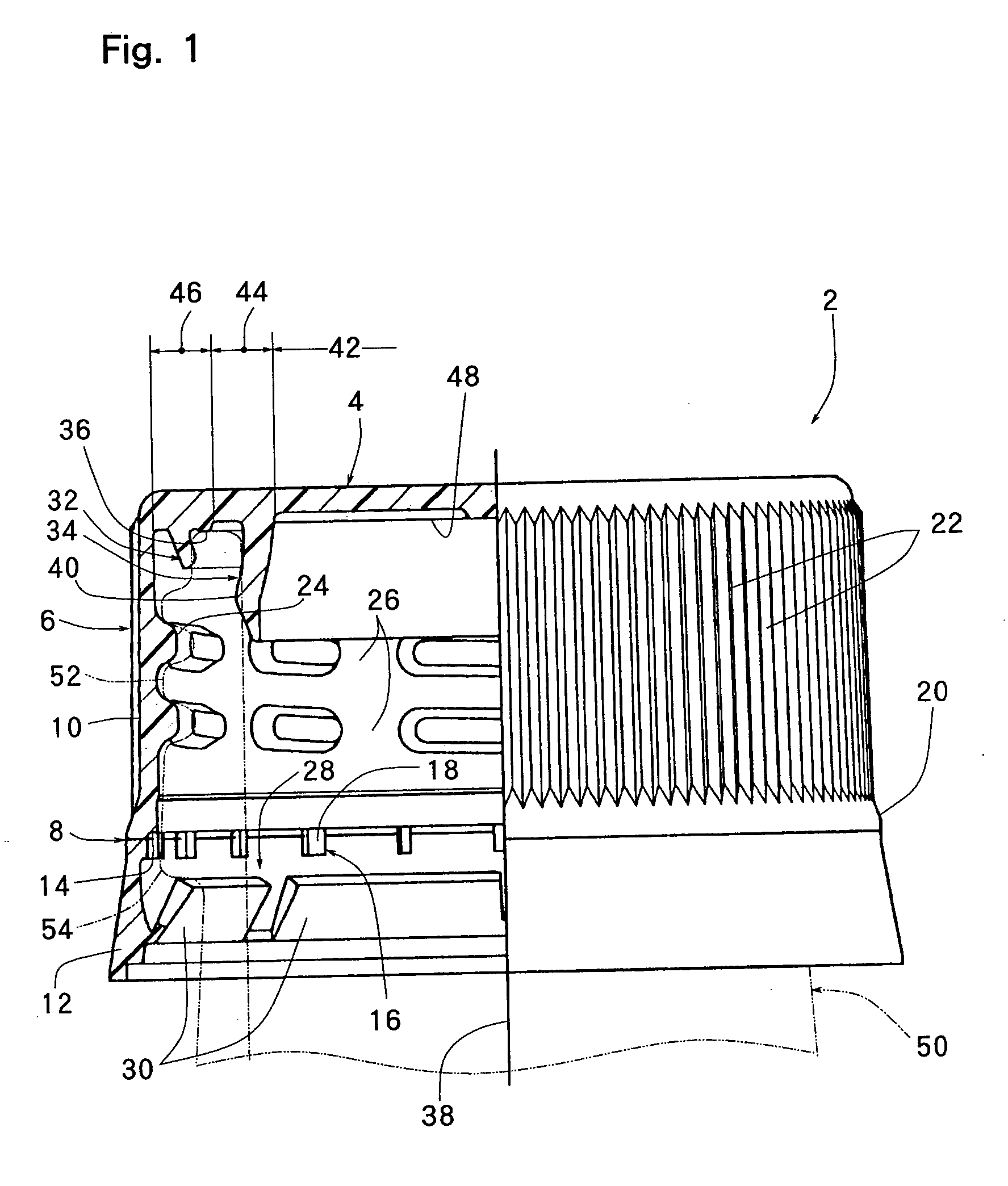
"The present invention relates to a synthetic resin container closure that has a circular top panel wall and a cylindrical skirt wall extending downwardly from the top panel wall. The closure has one or two cylindrical sealing protrusions that extend downwardly from the inner surface of the top panel wall. The closure is designed to be mounted on a container by screwing onto a mouth-neck portion of the container. When the closure is mounted, the mouth-neck portion is sealed hermetically without fail and the closure can be easily removed without excessive torque. The closure is formed from a single synthetic resin material and has a weakening line that breaks when the closure is turned in an opening direction. The weakening line is important for releasing the sealing of the mouth-neck portion after the closure is turned. The invention solves the problem of deformation in the top panel wall caused by the required cooling time in the mold."
Problems solved by technology
However, the above container closure of the prior art involves the following problems to be solved.
Therefore, in the above container closure of the prior art, there is a tendency that the sealing of the mouth-neck portion is released before the container closure is turned at a predetermined rotation angle owing to the production tolerance of the container closure and / or the mouth-neck portion or owing to the thermal deformation of the container closure and / or the mouth-neck portion, and there may occur a case where the above basic requirement can not be satisfied.
Secondly, the above container closure is formed from an appropriate synthetic resin by compression molding or injection molding.
However, when the thickness of the top panel wall, particularly the center portion thereof, is reduced, another problem arises as follows.
When the space between the top surface of the mandrel and the peripheral surface of the printing roller is made large to prevent this situation, the amount of compression of the printing roller at the time when the printing roller is applied to the outer surface of the top panel wall of the container closure mounted on the mandrel becomes too small, thereby making it impossible to carry out satisfactory printing in a case where the outer surface of the top panel wall has some general permissible distortion.
Further, if the thickness of the top panel wall, particularly the center portion, is reduced, the rigidity of the top panel wall is inevitably reduced, whereby the so-called flexibility of the inner cylindrical sealing protrusion becomes too large, contact pressure between the inner cylindrical sealing protrusion and the inner peripheral surface of the mouth-neck portion of the container becomes too small, and hence the hermetical sealing of the mouth-neck portion is liable to be insufficient.
As is well known to people having ordinary skill in the art, after the synthetic resin container to be filled with contents heated at approximately 80 to 95.degree. C. is molded into a predetermined shape, the mouth-neck portion thereof is crystallized by heating, thereby slightly reducing the dimensional accuracy of the mouth-neck portion.
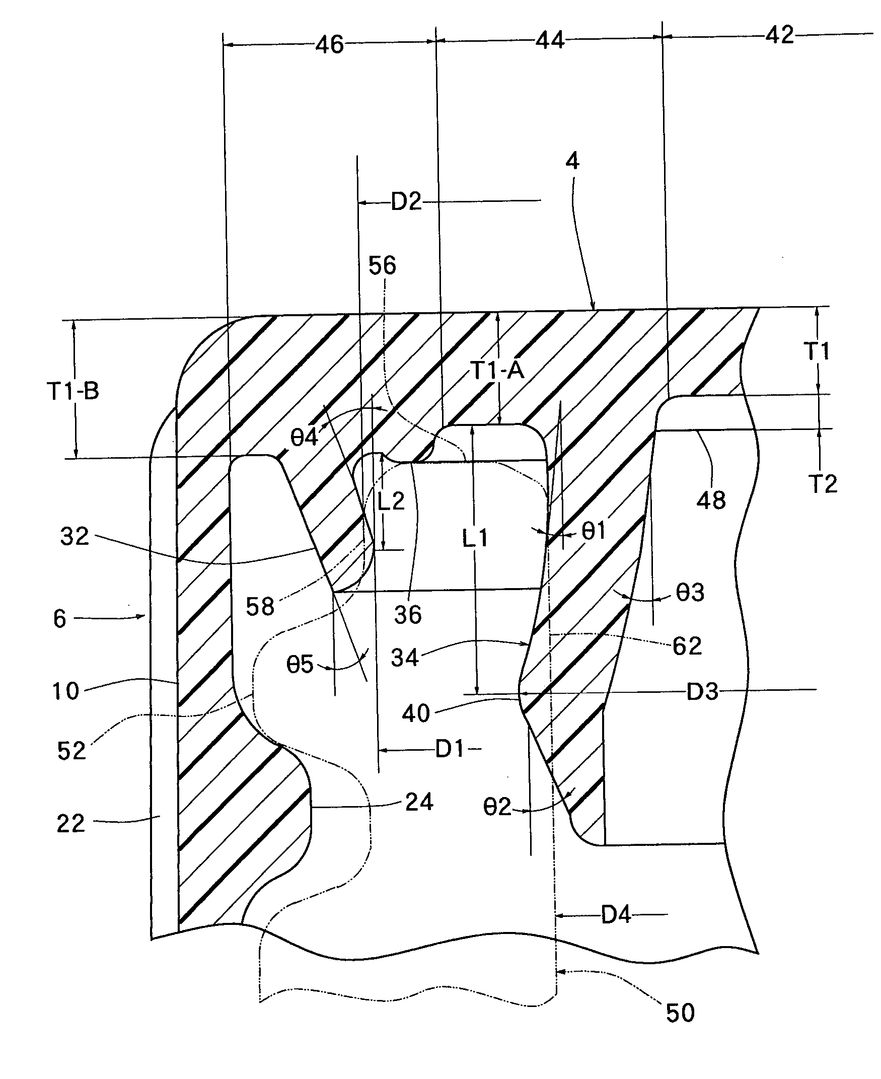
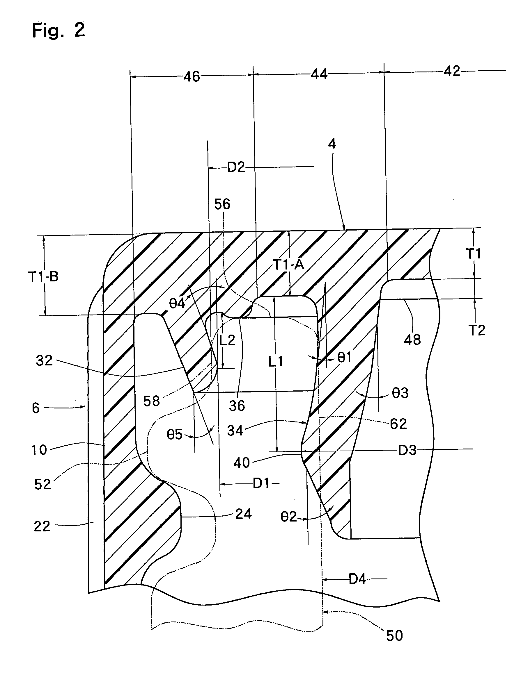
If (D2-D1) and (D3-D4) are too small, a tendency occurs that the hermetical sealing of the mouth-neck portion may become unsatisfactory, and at the same time the sealing of the mouth-neck portion may be released before the container closure is turned at a required rotation angle to open the mouth-neck portion.
On the other hand, if (D2-D1) and (D3-D4) are too large, there is a tendency that torque to be applied to the container closure to open the mouth-neck portion may become excessive.
If the thickness T1 of the center portion of the top panel wall is too large, the thickness T2 of each of the ribs is too large, or the total of the thickness T1 of the center portion of the top panel wall and the thickness T2 of each of the ribs is too large, the cooling time required for preventing deformation larger than the permissible range in the top panel wall will become long.
If the thickness T1 of the center portion of the top panel wall is too small, the rigidity of the top panel wall will become too low and the hermetical sealing of the mouth-neck portion of the container will become insufficient.
If the thickness T2 of each of the ribs is too small or the total of the thickness T1 of the center portion of the top panel wall and the thickness T2 of each of the ribs is too small, the rigidity of the top panel wall will become too low and at the same time, it becomes necessary to set the space between the top surface of a mandrel and the peripheral surface of a printing roller to an extremely small value in the printing step, and there is a possibility that the inner surface of the center portion of the top panel wall is stained by a printing ink as described above.
If (D3-D4) is too small, a tendency occurs that the hermetical sealing of the mouth-neck portion may become unsatisfactory and at the same time, the hermetical sealing of the mouth-neck portion may be released before the container closure is turned at a required rotation angle to open the mouth-neck portion.
On the other hand, if (D3-D4) is too large, there is a tendency that torque to be applied to the container closure to open the mouth-neck portion may become excessive.
If the thickness T1 of the center portion 42 is too small, the rigidity of the top panel wall 44 may become too low and the hermetical sealing of the mouth-neck portion of the container may become insufficient.
Further, the following problem arises in the printing step.
Method used
View moreImage
Smart ImageViewing Examples

Examples
example 2
[0059] The initial torque and the angles B and L were measured in the same manner as in Example 1 except that D3 of the container closure was 21.41 mm and (D3-D4) was 0.81 mm. The results are shown in Table 2.
example 3
[0060] The initial torque and the angles B and L were measured in the same manner as in Example 1 except that D3 of the container closure was 22.00 mm and (D3-D4) was 1.40 mm. The results are shown in Table 3.
example 4
[0063] The angles B and L were measured in the same manner as in Example 1 except that D1 of the container closure was 24.84 mm and (D2-D1) was 0.10 mm. The results are shown in Table 6.
Login to View More PUM
| Property | Measurement | Unit |
|---|---|---|
| inclination angle θ2 | aaaaa | aaaaa |
| inclination angle θ2 | aaaaa | aaaaa |
| length L1 | aaaaa | aaaaa |
Abstract
A container closure formed from a synthetic resin as a single unit has a circular top panel wall and a cylindrical skirt wall extending downwardly from the peripheral edge of the top panel wall. An outer cylindrical sealing protrusion, an inner cylindrical sealing protrusion, and annular sealing ridge, all having a predetermined shape and a predetermined size, are formed on the inner surface of the top panel wall. In one embodiment, the thickness of the center portion of the top panel wall is reduced to a predetermined range and a plurality of ribs having a predetermined thickness are formed on the inner surface of the center portion of the top panel wall.
Description
[0001] This application is a divisional application of Ser. No. 09 / 804,267 filed Mar. 13, 2001.[0002] The present invention relates to a synthetic resin container closure formed from a synthetic resin material as a single unit and, more specifically, to a synthetic resin container closure which has a circular top panel wall and a cylindrical skirt wall extending downwardly from the peripheral edge of this top panel wall, one or two cylindrical sealing protrusions that extend downwardly being formed on the inner surface of the top panel wall.DESCRIPTION OF THE PRIOR ART[0003] A synthetic resin container closure which is wholly formed from an appropriate synthetic resin such as polypropylene or polyethylene as a single unit has been proposed as a container closure for drink or beverage containers and has been put to practical use. The container closure has a circular top panel wall and a cylindrical skirt wall extending downwardly from the peripheral edge of this top panel wall, and o...
Claims
Login to View More Application Information
Patent Timeline
 Patent Type & AuthorityApplications(United States)
IPC IPC(8): B65D41/04B65D41/32B65D41/34
CPCB65D41/0421Y10S215/01B65D41/3428B65D41/325B65D41/34
InventorKANO, YUJINAKAJIMA, HISASHI
OwnerJAPAN CROWN CORK CO LTD