Image formation device

Active Publication Date: 2006-12-28
FUJIFILM BUSINESS INNOVATION CORP
View PDF6 Cites 10 Cited by
  • Summary
  • Abstract
  • Description
  • Claims
  • Application Information

AI Technical Summary

Benefits of technology

[0007] In consideration of the circumstances described above, the present invention will provide an image formation device in which a belt body does not become an obstacle at times of mounting / removal of process cartridges.
[0012] Therefore, when the cover body opens up the lateral direction side of the process cartridges, the belt body can be moved further from the process cartridges than in a case in which a belt body is axially supported at a side of a device main body, and the belt body will not be an obstacle at times of mounting / removal of the process cartridges.

Problems solved by technology

Hence, the belt body is an obstacle at times of mounting / removal, particularly of a lowest of the process cartridges.
Moreover, at times of mounting / removal of the process cartridges, the belt body may be soiled by toner which leaks from the process cartridges.

Method used


Image

  • Image formation device
  • Image formation device
  • Image formation device

Examples


Embodiment Construction

[0018] Herebelow, an example of an embodiment relating to an image formation device of the present invention will be described in accordance with the drawings.

[0019] First, overall structure of an image formation device 10 of the present embodiment will be described.

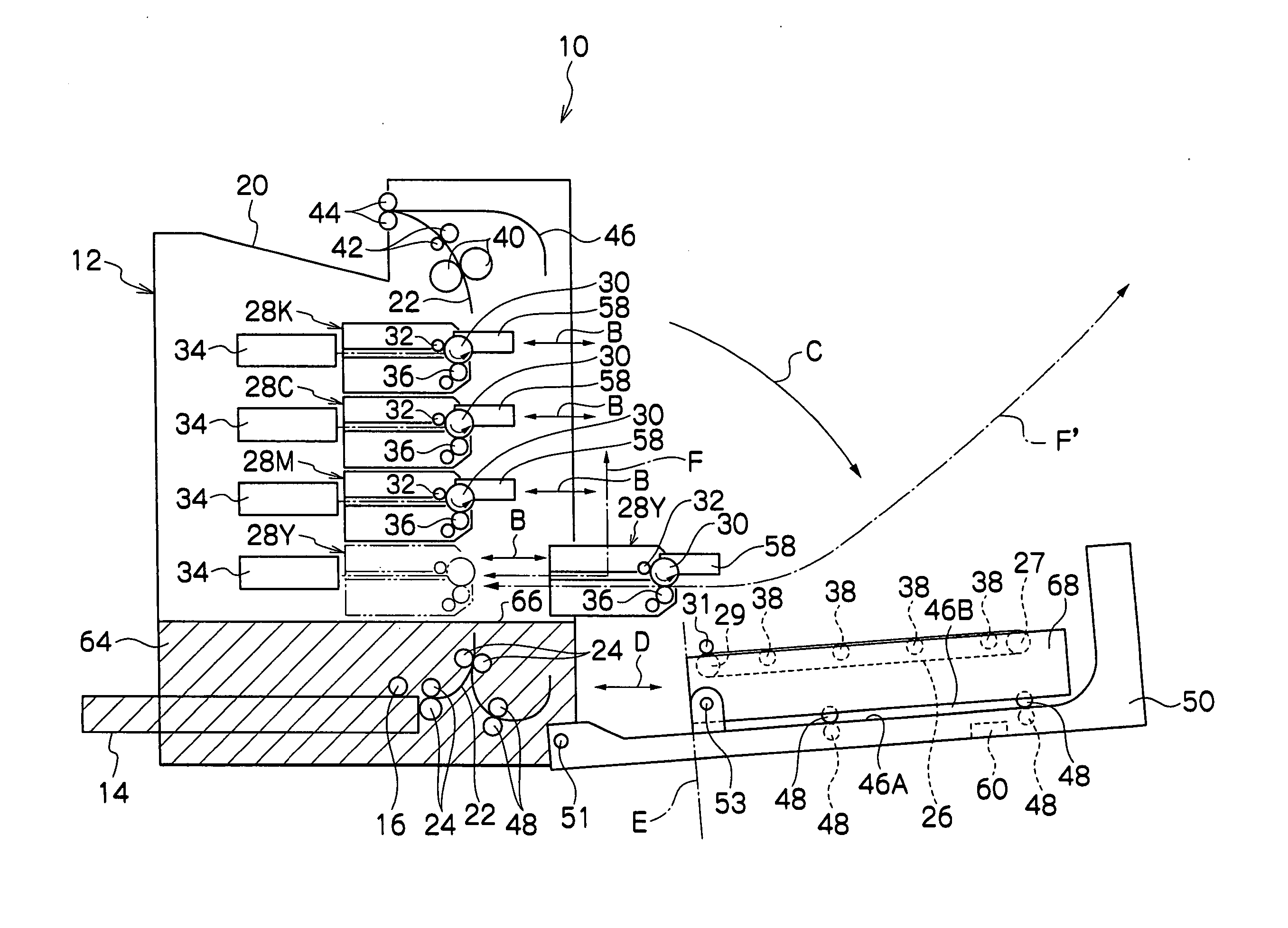
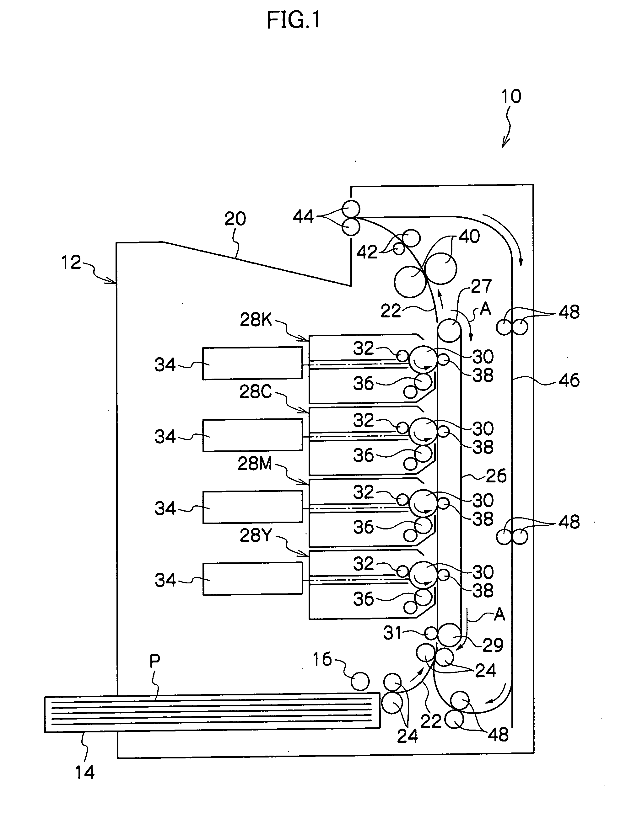
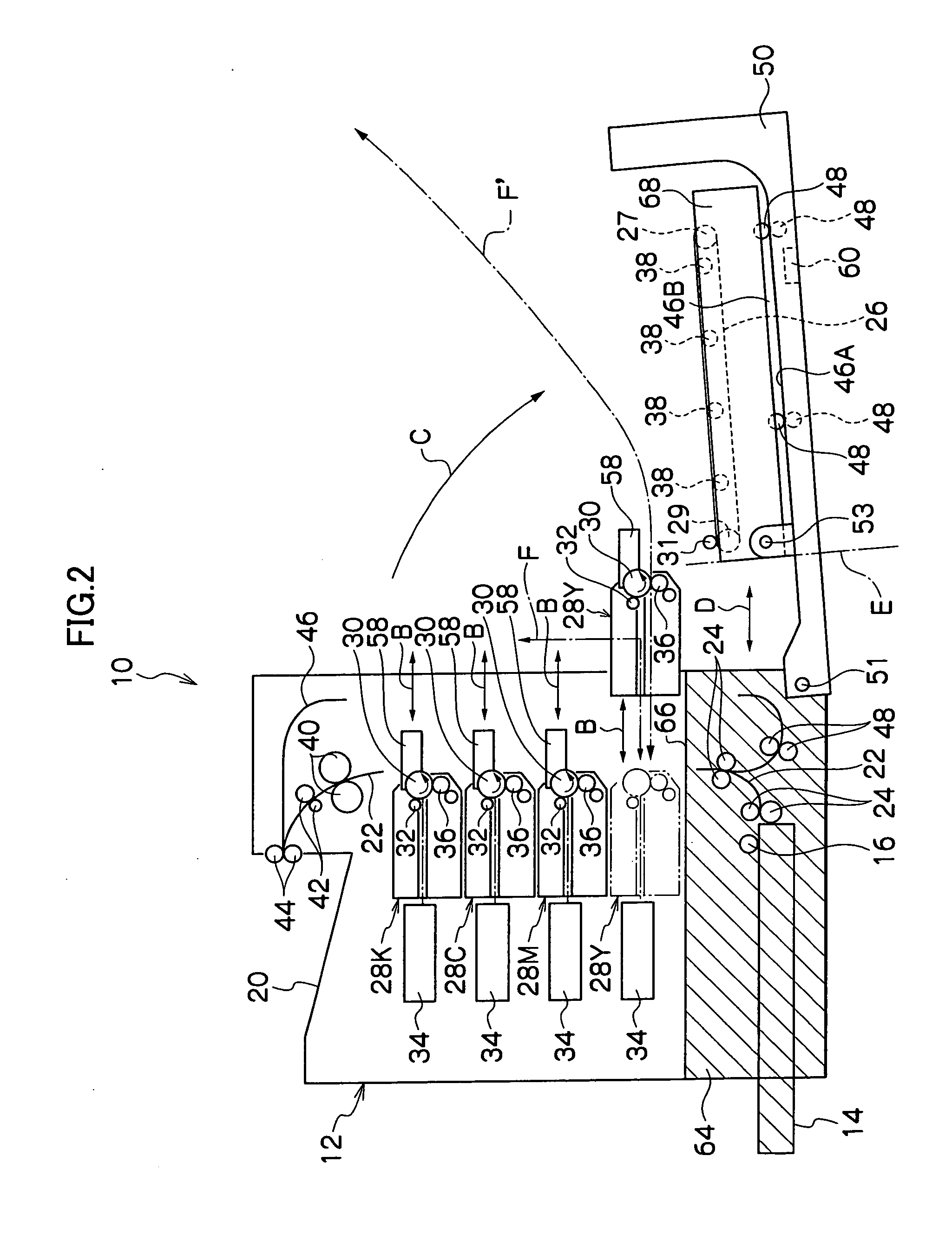
[0020] As shown in FIGS. 1 and 2, the image formation device 10 of the present embodiment is provided with a device main body 12. A paper supply section 64 (the shaded portion in FIG. 2) is provided at a lower portion of the device main body 12. The paper supply section 64 supplies paper P (a recording medium) to an image formation section (between process cartridges 28Y, 28M, 28C and 28K and a transport belt 26, which are described later).

[0021] The paper supply section 64 is formed in a box shape, being a paper supply cassette which can be mounted / removed in a direction D. A paper tray 14 is disposed at the paper supply section 64. The paper P is stacked in a sheaf at the paper tray 14.

[0022] A feed roller 16 is di...


PUM


Abstract

A plurality of process cartridges are provided at a device main body. The process cartridges are arranged in tandem in a vertical direction, and are each mountable / removable by being withdrawn in a horizontal direction. A transport belt is disposed near side portions of the process cartridges. The transport belt transports paper between the transport belt and each of the process cartridges. A cover covers the side portions of the process cartridges and is axially supported at the device main body, below the process cartridges, to be swingable. The cover is attached to be capable of opening and closing a process cartridge side portions side of the device main body. The belt is mounted at the cover so as to be disposed between the process cartridges and the cover, and operates integrally with the cover.

Description

CROSS-REFERENCE TO RELATED APPLICATION [0001] This application claims priority under 35 USC 119 from Japanese Patent Application No. 2005-184468, the disclosure of which is incorporated by reference herein. BACKGROUND OF THE INVENTION [0002] 1. Field of the Invention [0003] The present invention relates to an image formation device which forms an image on a recording medium. [0004] 2. Description of the Related Art [0005] An image formation device for forming an image on a recording medium is known which is provided with a plurality of process cartridges, which are provided at a main body of the device to be mountable and removable in a lateral direction (horizontal direction), and which are arranged in tandem (see, for example, Japanese Patent Application Laid-Open (JP-A) No. 2003-241616). A belt body, which is disposed at a lateral direction side of these process cartridges (a side of side portions of the process cartridges), is swung to open up the lateral direction (side portion...

Claims


Application Information

Patent Timeline
IPC IPC(8): G03G15/00
CPCG03G21/16G03G2221/183G03G2221/1687G03G21/1633G03G15/00
Inventor OZAWA, TORU
Owner FUJIFILM BUSINESS INNOVATION CORP
Why Eureka
Try Eureka