
Pan cleaning machine and a method of operating the machine to clean pans

a technology of cleaning machine and pan, which is applied in the direction of cleaning equipment, washing/rinsing machines, brushes, etc., to achieve the effect of reducing downtim

Pending Publication Date: 2021-04-29
SCHMIDT NORMAN +1
View PDF0 Cites 1 Cited by
  • Summary
  • Abstract
  • Description
  • Claims
  • Application Information

AI Technical Summary

Benefits of technology

The patent describes an improved pan cleaning machine that has a cleaning section with multiple frames for mounting different cleaning mechanisms. The frames can be quickly changed to adapt to different types of pans or to replace worn parts. The cleaning mechanisms can be swung away from the baking surface when not in use, allowing for continuous operation without stopping the machine. The machine also has a discharge section and a plurality of frames for mounting interchangeable modular cleaning mechanisms, making it more adaptable for different cleaning needs. The cleaning mechanisms can be programmed into the machine control system to automatically switch them without human error. The improved pan cleaning machine is efficient, effective, and adaptable for cleaning pans in high-volume manufacturing processes.

Problems solved by technology

If debris that is transferred to brush bristles or other cleaning elements is allowed to build up, then sticky or oily debris can be transferred back to the pans, and this can be a problem if the debris includes ingredients that could be allergens.

Method used


Image

  • Pan cleaning machine and a method of operating the machine to clean pans
  • Pan cleaning machine and a method of operating the machine to clean pans
  • Pan cleaning machine and a method of operating the machine to clean pans

Examples


Embodiment Construction

)

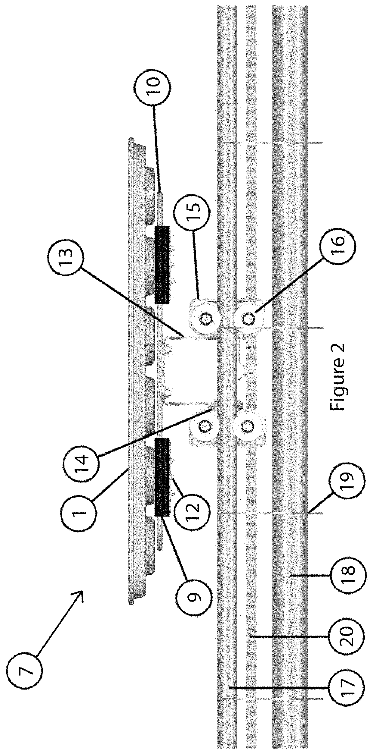
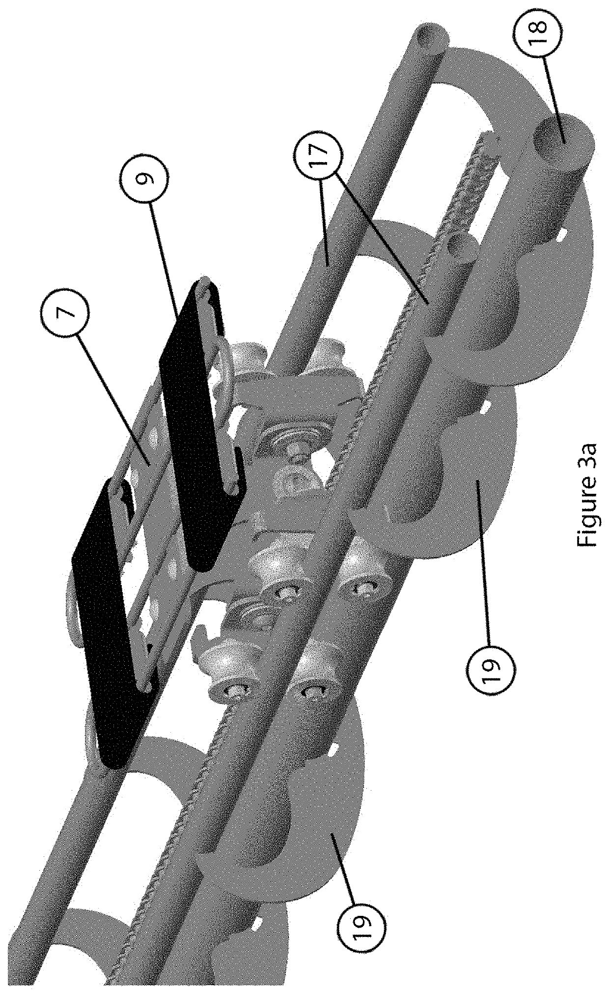
[0032]The following detailed description represents embodiments that are intended to provide an overview or framework for understanding the nature and character of the disclosed pan cleaning machine and method. The accompanying drawings are included to provide further understanding of the disclosed apparatus and method and constitute part of the specification. Accordingly, the detailed descriptions and drawings are non-limiting to the scope of the concepts that are disclosed and are intended to illustrate and explain the principles and operations of the apparatus and method, as exemplified by these embodiments.

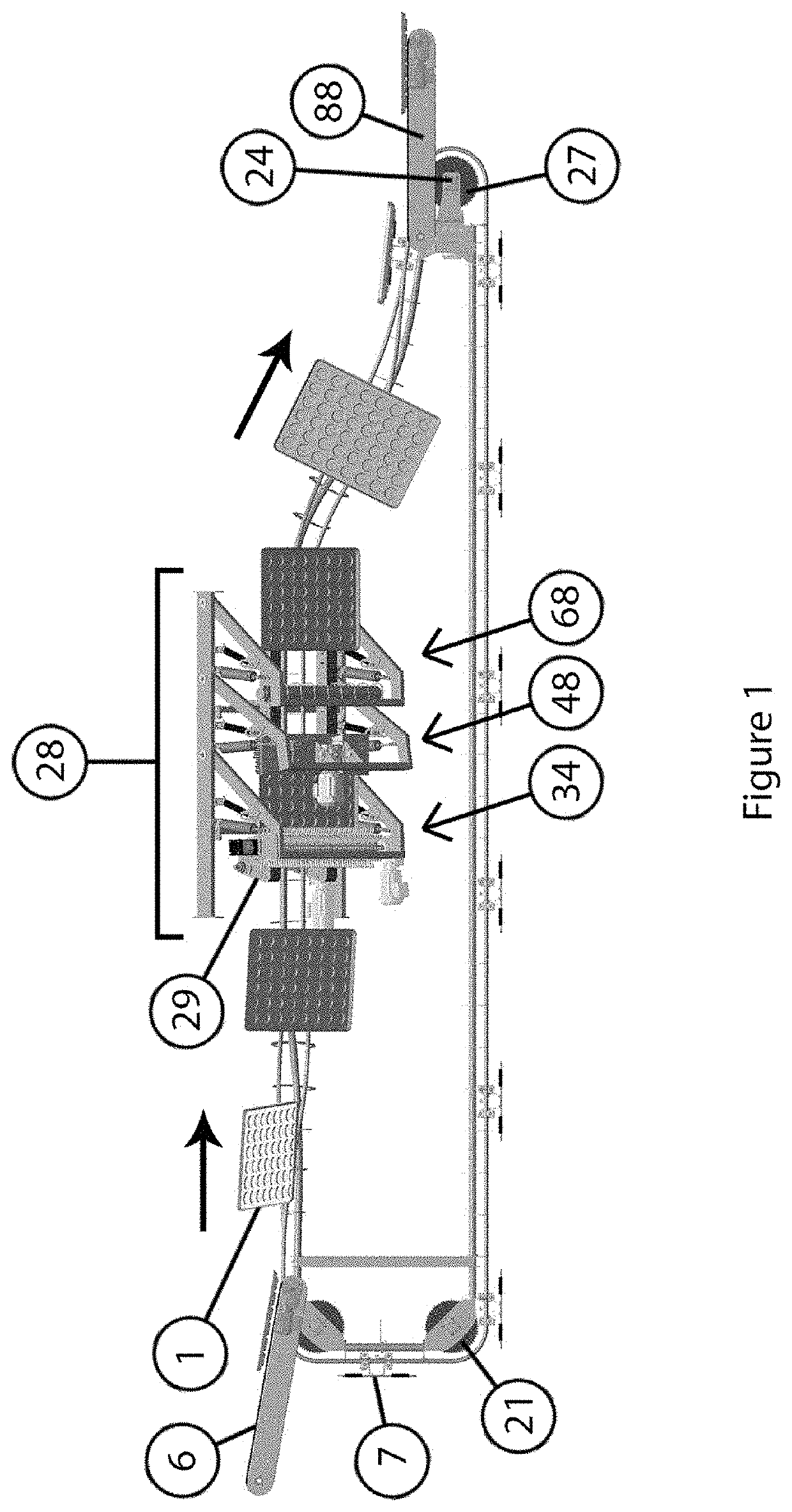
[0033]Referring to FIG. 1, a side view of a pan cleaning machine is shown. In the illustrated example, the pan cleaning machine is used to clean baking pans, such as those used in commercial mass production bakeries. This example is used in this disclosure to illustrate the claimed concepts, but it will be understood that the disclosed machine and method can be applied to oth...


PUM


Abstract

The invention is directed to an improved pan cleaning machine that has a cleaning section that comprises a plurality of frames for mounting a sequence of interchangeable modular cleaning mechanisms. It can include quick-release mounting arrangements so that cleaning mechanisms can be quickly changed for cleaning different types of pans or to replace brushes or other wearing parts of cleaning mechanisms when they require replacement. In some embodiments, the frames for mounting the cleaning mechanisms can comprise swing arms so that the cleaning mechanisms can be swung away from the cleaning position so that the cleaning mechanism can be removed and replaced without interrupting the operation of the machine. If the machine is stopped, the swing arm can still be used to facilitate access to the cleaning mechanism to reduce the time needed to complete the maintenance or replacement. This also allows the position of the cleaning mechanism in relation to the baking pans to be adjustable during the cleaning process which can permit increased application of brushing forces or prevent overloading and also permits easy jam removal. In addition, the swing arm makes the pan cleaning machine more adaptable for cleaning pans with different depths and customizable. A method of operation and control, including pre-programmed cleaning cycles and various control paradigms is also provided.

Description

CROSS REFERENCE TO RELATED APPLICATIONS[0001]This application claims the priority of U.S. provisional patent application 62 / 894,915, filed Sep. 2, 2019, which is incorporated herein by reference.FIELD OF THE INVENTION[0002]The present application relates to a pan cleaning machine with pans transported on rolling carriages and a method of using such a machine to clean pans. More specifically, the disclosed pan cleaning machine enables a method of continuous automated pan cleaning, and the rolling carriage arrangement enables the pans to be positioned in different orientations more complex than known machines, to facilitate removal of debris from the pans and improve cleaning.BACKGROUND OF THE INVENTION[0003]Baking pans used in mass production bakeries are an example of an application for the disclosed machine and method of operation. It is not uncommon for modern mass production bakeries to have production rates of 1,600 buns per minute, which amounts to about 33 baking pans each min...

Claims


Application Information

Patent Timeline
IPC IPC(8): A47L15/46A47L15/24A47L15/00A47L15/39A47L15/42A46B13/02A46B13/00
CPCA47L15/46A47L15/241A47L15/0092A47L15/0076A47L15/39A46B2200/3006A46B13/023A46B13/001A47L2401/04A47L2401/24A47L2401/17A47L15/4282A46B9/025A46B9/028A46B2200/30A46B2200/3073A21B3/16
Inventor SCHMIDT, NORMANJANZEN, ORLANDO
Owner SCHMIDT NORMAN
Learn More