
Vehicle speed monitoring system

a technology of speed monitoring system and vehicle, which is applied in the direction of electric/magnetic computing, analogue processes for specific applications, instruments, etc., can solve the problems of easy distraction and failure of drivers, speed limits and driving conditions along any given route may change frequently, and speed limits may change according to speed limits

Active Publication Date: 2007-01-04
GM GLOBAL TECH OPERATIONS LLC
View PDF19 Cites 238 Cited by
  • Summary
  • Abstract
  • Description
  • Claims
  • Application Information

AI Technical Summary

Benefits of technology

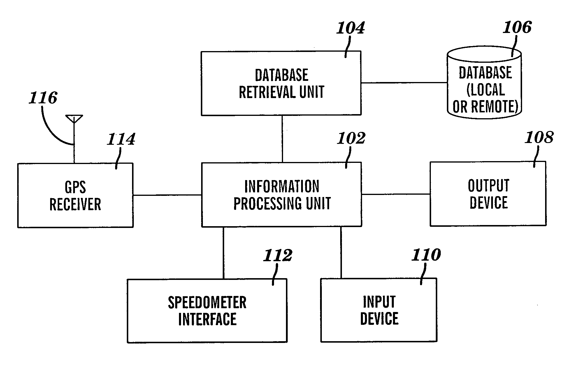
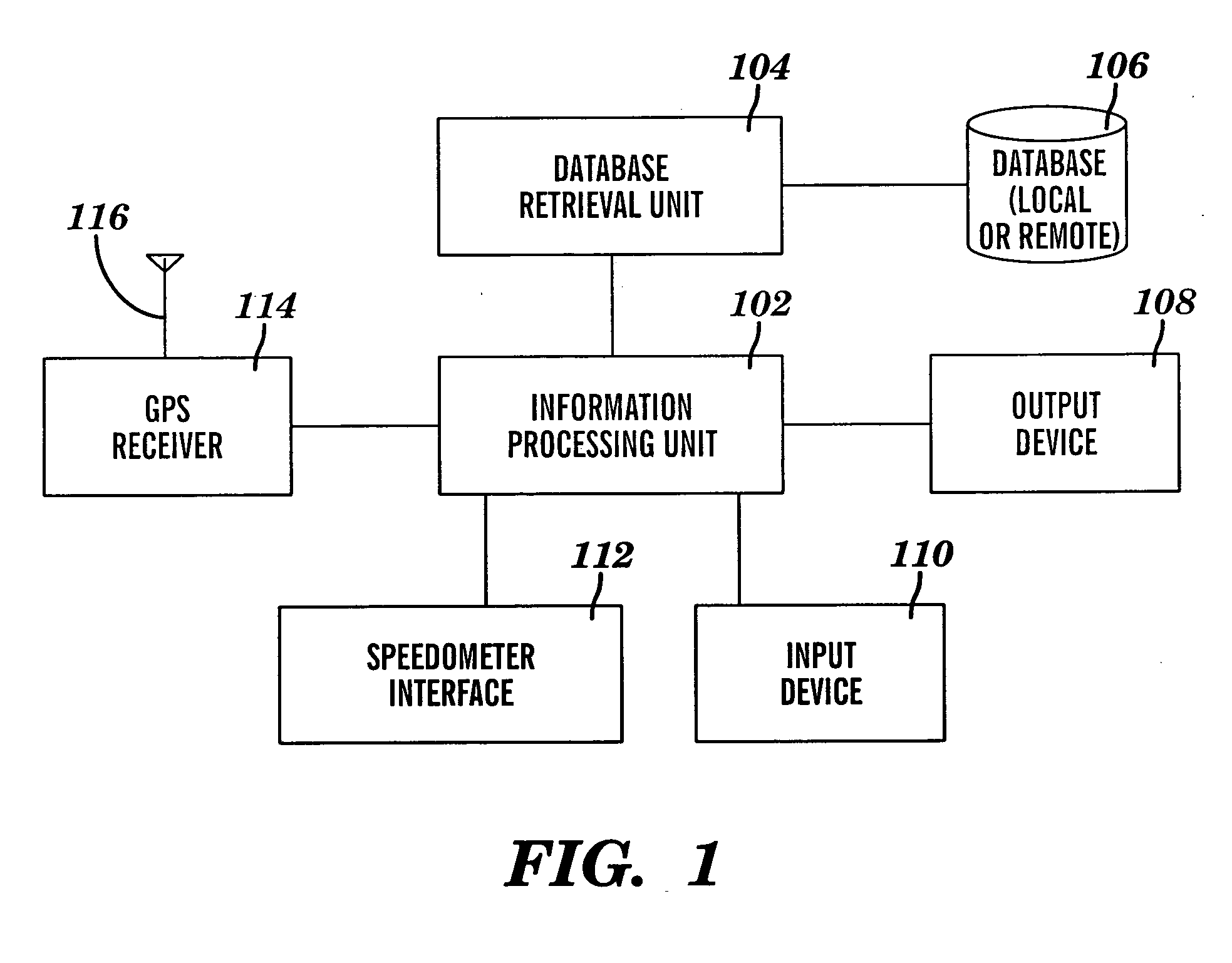
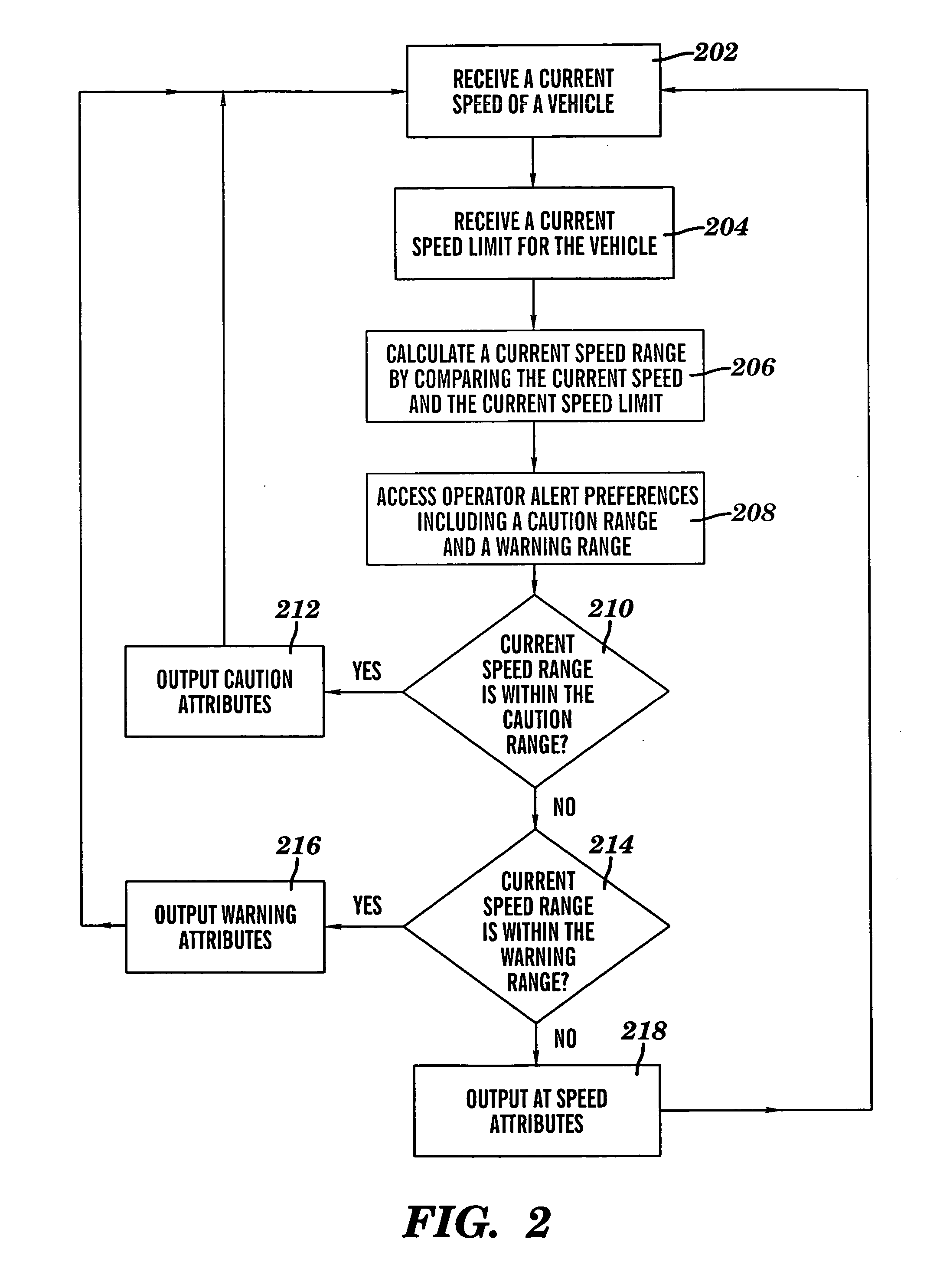
The invention provides a method, system, and computer program product for monitoring vehicle speed. The system receives the current speed of a vehicle and its associated speed limit, calculates the current speed range based on the speed limit and the vehicle's current speed, and accesses operator alert preferences that include a caution range and a warning range. The system then sends an alert to the operator of the vehicle that includes attributes based on the current speed range. This alert can include caution attributes when the current speed range is within the caution range, warning attributes when the current speed range is within the warning range, or at-speed attributes when the current speed range is not within the caution or warning range. The technical effect of this invention is to provide a system for monitoring vehicle speed and alerting the operator of the vehicle in real-time when they exceed the speed limit, which can help to improve safety on the road.

Problems solved by technology

Speed limits and driving conditions along any given route may change frequently, particularly in urban settings.
In addition, along a given route, speed limits may change according to the time of day, such as during school hours or rush hours.
However, it is easy for drivers to become distracted and not notice changes in speed limit sign postings.

Method used


Image

  • Vehicle speed monitoring system
  • Vehicle speed monitoring system
  • Vehicle speed monitoring system

Examples


Embodiment Construction

[0017] Exemplary embodiments of the present invention provide a caution message (visual, audio and / or haptic) to an operator of a vehicle when the current speed of the vehicle is approaching a driver specified maximum speed. In addition, a warning message (with different attributes than the caution message) is provided to the operator of the vehicle when the current speed of the vehicle has exceeded the driver specified maximum speed. This two step, or multiple stage alert, provides the operator with an opportunity to slow the vehicle down before exceeding his or her preferred maximum traveling speed.

[0018] For example, an operator may specify a caution range to include speeds ranging from the posted speed limit to ten miles over the posted speed limit. A caution attribute may include displaying a textual depiction of the current vehicle speed in a yellow text. Therefore, when the vehicle is traveling in the specified caution range, the current speed of the vehicle will be depicted...


PUM


Abstract

A method for monitoring vehicle speed is provided. The method includes receiving a current speed of a vehicle and a current speed limit associated with a current location of the vehicle. A current speed range is calculated by comparing the current speed of the vehicle to the current speed limit. Operator alert preferences including a caution range and a warning range are accessed. An alert responsive to the current speed range and to the operator alert preferences is communicated to the operator of the vehicle. The alert includes one or more caution attributes when the current speed range of the vehicle is within the caution range. The alert includes one or more warning attributes when the current speed range of the vehicle is within the warning range. The alert includes one or more at speed attributes when the current speed range of the vehicle is not within the caution range or the warning range.

Description

BACKGROUND OF THE INVENTION [0001] The present disclosure relates generally to a vehicle speed monitoring system, and more particularly, to providing a vehicle operator with different alerts when the vehicle is approaching an operator specified maximum speed and when the vehicle exceeds the operator specified maximum speed. [0002] Speed limits and driving conditions along any given route may change frequently, particularly in urban settings. In addition, along a given route, speed limits may change according to the time of day, such as during school hours or rush hours. [0003] The most widely used method of informing a vehicle driver of the speed limit of a particular road is through posted speed limit signs on the side of the road. However, it is easy for drivers to become distracted and not notice changes in speed limit sign postings. Moreover, when multiple speed limit signs are posted for a single section of a road (e.g., a school hour speed limit and a non-school hour speed lim...

Claims


Application Information

Patent Timeline
Patent Type & Authority Applications(United States)
IPC IPC(8): B60Q1/00
CPCB60K31/185G01P1/103B60W2550/22B60W2555/60B60W2050/143
Inventor DAGCI, OGUZ H.GRIMM, DONALD K.SADEKAR, VARSHABARTZ, DANIEL J.HERMIZ, SARMAD Y.HAMILTON, WILLIAM E.
Owner GM GLOBAL TECH OPERATIONS LLC
Learn More